
Specifications

Electrical Specifications
Rev 8 Apr.14 Proprietary and Confidential - Contents subject to change 29
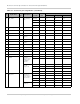
46 DPR/
GPIO4
- (DPR)
Dynamic power
control
Input High 1.17 1.80 2.10
Input Low -0.30 - 0.63
(GPIO4)
General
purpose I/O
Input High 1.17 1.80 2.10
Input Low -0.30 0.63
Output High 1.35 1.80 1.90
Output Low 0.00 0.45
47 PCM_DOUT/
I2S_DOUT
6
- PCM Data Out/
I
2
S Data Out
Output High 1.35 1.80 1.90
Output Low 0 0.45
48 NC - No connect - - - - -
49 PCM_DIN/
I2S_DIN
6
- PCM Data In/
I
2
S Data In
Input High 1.17 1.80 2.10
Input Low -0.30 0.63
50 GND V Ground Input Power - 0 -
51 PCM_WS /
I2S_SYNC
6
- PCM Sync—
Input in Slave
mode, output in
Master mode
Input High 1.17 1.80 2.10
Input Low -0.30 0.63
Output High 1.35 1.80 1.90
Output Low 0.00 0.45
I
2
S WS Output High 1.35 - 1.90
Output Low 0 - 0.45
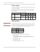
52 VCC V Power supply Input Power 3.00 3.30 3.60
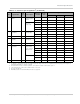
1. The host should leave all ‘NC’ (‘no connect) pins unconnected.
2. A—Analog; I—Input; NP—No pull; O—Digital output; OC—Open Collector; PU—Digital input (internal pull up); PD—Digital out-
put (internal pull down); V—Power or ground
3. To avoid adverse effects on module operation, do not draw more than 10 mA current on pin 11.
4. Leave both I2C pins as No Connect if I2C interface is not used.
5. Clock speed: 400 kHz
6. PCM Master/Slave mode and I2S Master mode are supported.
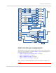
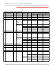
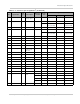
Table 3-1: Connector pin assignments
1
(Continued)
Pin Signal name
Pin
type
2
Description
Direction
to module
Active
state
Voltage levels (V)
Min Typ Max