
Specifications


Rev 8 Apr.14 Proprietary and Confidential - Contents subject to change 23
3
3: Electrical Specifications
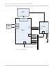
The system block diagram in Figure 3-1 on page 24 represents the
MC7304 module integrated into a host system. The module includes
the following interfaces to the host:
•
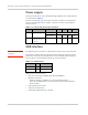
Power—Supplied to the module by the host.
•
W_DISABLE_N—Active low input from a hardware switch to the
MC7304 that disables the main RF radio.
•
WAKE_N— Signal used to wake the host when specific events
occur.
•
WAN_LED_N—Active-low LED drive signal provides an indication
of RADIO ON state, either WAN or GNSS.
•
SYSTEM_RESET_N—Active-low reset input.
•
Antenna—Three U.FL RF connectors (one for Rx/Tx, one for Rx
only, and one for GNSS). For details, see RF Specifications on
page 41.
•
SIM—Supported through the interface connector. The SIM
cavity / connector must be placed on the host device for this
feature.
•
USB—Interface to the host for data, control, and status infor-
mation.
•
Antenna control—Three signals that can be used to control
external antenna switches.
•
Dynamic power control—Signal used to adjust Tx power to meet
CE SAR requirements. For details, see Tx power control on
page 57.
•
PCM/I
2
S audio interface —PCM or Inter-IC Sound (I
2
S) serial bus
for digital audio.
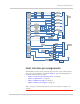
The MC7304 has two main interface areas—the host I/O connector
and the RF ports. Details of these interfaces are described in the
sections that follow.