
User manual

GHI Electronics,LLC Embedded Master User Manual
Hardware and Software Library
Example
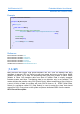
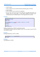
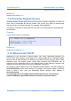
Analog Output
// Use analog output, initial output value is 500. The user would write values with
// a minimum of 100 and maximum of 2000
AnalogOut analogOutput = new AnalogOut(500, 100, 2000)
// write 2000, this gives maximum value to the output pin
analogOutput.Write(2000);
Reference
GHIElectronics.Hardware.AnalogIn
GHIElectronics.Hardware.AnalogOut
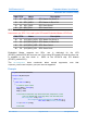
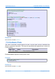
11.8. PWM
Five (2 on the Non-TFT version) PWM pins are exposed with native functions support.
Embedded Master PWM pins are clocked by two separate timers (0 and 1). Thus, PWM
lines with the same clock can have different pulse widths, but the user must be aware that
changing one's clock will affect the other PWM channel with the same clocksource .
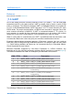
PIN# Name Description
16 PWM0.0 PWM 0 ( PWM Timer 0 )
17 PWM1.1 PWM 1 ( PWM Timer 1 )
35 – TFT Version Only PWM1.4 PWM 4 ( PWM Timer 1 )
39 – TFT Version Only PWM1.3 PWM 3 ( PWM Timer 1 )
40 – TFT Version Only PWM0.2 PWM 2 ( PWM Timer 0 )
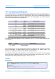
The user would first initialize the needed PWM channel and then set the needed frequency
and duty cycle which can be set to different values at anytime later. Duty Cycle value is a
percentage of the total period. Valid values are 0% to 100%, inclusive. Frequency can be
set to 0 to disable the PWM module. Other values less or equal to PWM.MAX_FREQUENCY
are also valid. Currently, the maximum is set to 10MHZ.
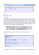
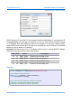
Example
// Initialize PWM 1
PWM pwmChannel1 = new PWM(PWM.PWMChannel.Channel_1);
// Set Freq to 1 KHZ and duty cycle to 50%
pwmChannel1.Set(1000, 50);
Rev. 2.06 TFT Page 68 of 102 www.ghielectronics.com