
User manual

GHI Electronics,LLC Embedded Master User Manual
Hardware and Software Library
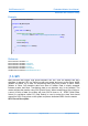
11.7. Analog Inputs/Outputs
The 7 (4 on the Non-TFT version) analog inputs continuously convert the analog value on
a particular pin and store the value in a local register. This is only activated after an analog
input object is created in the managed application. The analog inputs are 10-bit resolution
with 3.3V reference taken from input power.
PIN# Name Description
8 ADC1 Analog Digital Converter channel 1
9 ADC2 Analog Digital Converter channel 2
10 ADC3 Analog Digital Converter channel 3
11 ADC0 Analog Digital Converter channel 0
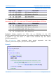
31 - TFT Version Only ADC6 Analog Digital Converter channel 6
32 - TFT Version Only ADC7 Analog Digital Converter channel 7
33 - TFT Version Only ADC5 Analog Digital Converter channel 5
ADC4 Not Available
The analog output can set the pin to any value from 0V to 3.3V (VCC to be exact) with 10-
bit resolution.
PIN# Name Description
10 AOUT Analog Output
For each analog pin, the user will specify the range of values that are read from an analog
input, or the range of values that are going to be written to an analog output. The
conversion to a proper resolution is done by the managed library.
For example, the analog input channel is 10-bit, values from 0 to 1023. The user would
specify the same or different range of maximum and minimum values such as 0 – 270. The
managed library linearly maps the range 0 - 1023 to 0 – 270.
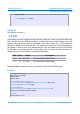
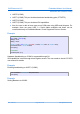
Example
Analog Input
// Use analog input 0. Make the range of read values start at 0 and end at 270
AnalogIn analogInput = new AnalogIn(AnalogIn.AnalogInputPin.AIN0, 0, 270);
// Read Value
int value = analogInput.Read(); // this value is between 0 and 270
Rev. 2.06 TFT Page 67 of 102 www.ghielectronics.com