
User manual

GHI Electronics,LLC Embedded Master User Manual
Hardware and Software Library
Example
// make a new bitmap
Bitmap myBitmap = new Bitmap(SystemMetrics.ScreenWidth,
SystemMetrics.ScreenHeight);
// draw a rectangle
myBitmap.DrawRectangle(Color.White, // color
1, // outline thickness
10, 10, // x, y
60, 50, // width, height
0, 0, // x, y corner radius
Colors.Black, // gradient start color
10, 10, // gradient start
Colors.White, // end color
80, 60, // gradient end
255); // opacity
myBitmap.Flush();
Reference
Microsoft.SPOT.Bitmap
Microsoft.SPOT.Presentation
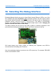
11.2. General Purpose I/O with External Interrupt
The module has 51 GPIO Pins + 20 on LCD Connector that can be freely used in
managed applications. All GPIO pins are 3.3V and 5V tolerant. This means that signals
coming from another circuit can be up to 5V (ie: connecting Embedded Master to a 5V
microcontroller). All pins support input and output with pull up and pull down.
31 Interrupt Inputs + 10 on LCD connector of these pins can also be used as interrupt pins.
Interrupt pins can asynchronously call functions in managed applications. Interrupts can be
activated on rising or falling edges with optional glitch filter. Enabling interrupts for both
rising and falling edges is supported but in this case the glitch filter is disabled. Interrupt
capable pins are marked in the pin-out table.
GPIO pins are available from GHIElectronics.Hardware.EmbeddedMaster.Pins
A pin can be defined as output, input or as an interrupt pin. Interrupts can be enabled on
Pins related to Port0 and Port2 on the LPC2478 chip, and other pins cannot have interrupt
enabled on.
Interrupt capable Pins have x appended to them. For example,
GHIElectronics.Hardware.EmbeddedMaster.Pins.E0x is interrupt capable, but
GHIElectronics.Hardware.EmbeddedMaster.Pins.E40 is not.
Rev. 2.06 TFT Page 60 of 102 www.ghielectronics.com