
User manual

GHI Electronics,LLC Embedded Master User Manual
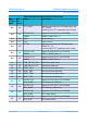
Pin-Out Description
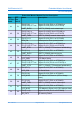
Embedded Master Module Pin-Out Description
Non-
TFT Rev
Pad #
TFT
Rev
Pad #
Name Description
53 63
E40 (P1.11) Digital I/O # 40 (P1.11 on LPC2468)
SD_DAT2 SD Memory Data 2
54 64
E41 (P1.7) Digital I/O # 41 (P1.7 on LPC2468)
SD_DAT1 SD memory Data 1
55 65
E42 (P1.2) Digital I/O # 42 (P1.2 on LPC2468)
SD_CLK SD memory Clock
56 66
E43 (P1.6) Digital I/O # 43 (P1.6 on LPC2468)
SD_DAT0 SD memory Data 0
57 67
E44 (P1.3) Digital I/O # 44 (P1.3 on LPC2468)
SD_CMD SD memory Command
58 68
SD_PWR SD memory power (connect directly to SD
power)
59 69 GND Power Ground
60 70 Reset# Active low Embedded Master Module reset
* Interrupt capable input.
(1)
Note: Usually USB VBUS signal is used to detect the USB physical connection thus it
can can be connected to any GPIO pin to detect the USB cable is connected or not.
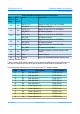
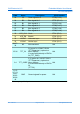
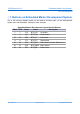
The flowing table shows the pin-out for the 0.5mm TFT display header.
PIN# Name Description GPIO Number
8 R0 Red signal bit 0 ET69*(P2.12)
9 R1 Red signal bit 1 ET65*(P2.6)
10 R2 Red signal bit 2 ET66*(P2.7)
11 R3 Red signal bit 3 ET67*(P2.8)
12 R4 Red signal bit 4 ET68*(P2.9)
15 G0 Green signal bit 0 ET51(P1.20)
16 G1 Green signal bit 1 ET52(P1.21)
17 G2 Green signal bit 2 ET53(P1.22)
18 G3 Green signal bit 3 ET54(P1.23)
19 G4 Green signal bit 4 ET55(P1.24)
Rev. 2.06 TFT Page 33 of 102 www.ghielectronics.com