
User manual

GHI Electronics,LLC Embedded Master User Manual
Pin-Out Description
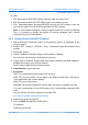
5. Pin-Out Description
Most signals on Embedded Master Module are multiplexed to offer more than one function
for every pin. It is up to the developer to select which one of the functions to use. GHI
drivers and .NET Micro Framework does some checking to make sure the user is not
trying to use two functions on the same pin. The developer should still understand what
functions are multiplexed so there is no conflict. For example, analog channel 3 (ADC3)
and the analog output (AOUT) are on the same pin. Either function can be used but not
both of them simultaneously.
Digital I/O pins are named Exx, where xx is an assigned number. GPIO pins for the TFT
version are named ETxx.
Make sure your design is made to accept the TFT / Non-TFT version of the modules. The
pads are compatible.
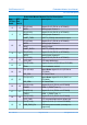
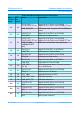
Embedded Master Module Pin-Out Description
Non-
TFT Rev
Pad #
TFT
Rev
Pad #
Name Description
1 1 3.3V Power source
2 2 GND Power Ground
3 3
E0 (P0.4)* Digital I/O # 0 (P0.4 on LPC2468)
CAN_RD2 CAN receive data channel 2
BTN_DN Default pin for down button
4 4
E1 (P0.5)* Digital I/O # 1 (P0.5 on LPC2468)
CAN_TD2 CAN transmit data channel 2
BTN_RT Default pin for right button
5 5
E2 (P0.3)* Digital I/O # 2 (P0.3 on LPC2468)
UART_RXD0 UART 0 (COM1) data receive input
6 6
E3 (P0.2)* Digital I/O # 3 (P0.2 on LPC2468)
UART_TXD0 UART 0 (COM1) data transmit output
7 7
E4 (P2.5*) or
E4 (P2.30*)TFT rev.
Digital I/O # 4 (P2.5 on LPC2468) or
Digital I/O # 4 (P2.30 on LPC24v8)
BTN_UP Default pin for up button
Rev. 2.06 TFT Page 28 of 102 www.ghielectronics.com