
User manual

GHI Electronics,LLC Embedded Master User Manual
Embedded Master Products
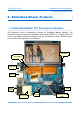
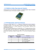
The schematics are the best reference for the development system. The next few sections
will explain the different parts of the development system. Take a look at the schematics
for further details.
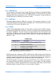
2.1.1 Input Power
It can be powered from the input power or the USB connector X1. Powering the system
from the USB cable is not recommended because of the voltage drop in the USB cables
and the USB Hubs. If using USB for power, connect the USB cable directly to the PC.
Connecting both the USB cable to X1 and power source to X7 is completely safe.
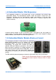
2.1.2 Ethernet
For network connectivity, the development system includes the required Ethernet
connector with built-in magnets.
2.1.3 USB Device (Virtual COM)
This is connected to a USB<->serial converter chip to COM1 of Embedded Master
Module. Drivers need to be loaded when this connector is plugged into the PC for the
first time.
Rev. 2.06 TFT Page 13 of 102 www.ghielectronics.com
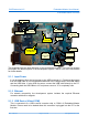
USB Host
Piezo
RTC Battery
SV4 Header
SV1 Header
Analog
Touch screen
pins
PWM/MISC
Embedded Master
TFT Module
LCD Header
LCD connector
TFT Connector
LED to PWM0
Reset Button