
DART 200 CDPD Modem User's Guide


DART 200 CDPD Modem User’s Guide E S-Registers
PN1197-00 Revision 1.0 E-3
Register definitions
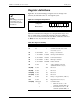
Figure E-1 shows that in bitmapped registers bit 7 is the high order
(leftmost) bit and bit 0 is the low order (rightmost) bit.
Figure E-1. S-Register bit positions
S-Register
Bit Position
7 6 5 4 3 2 1 0
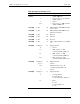
Table E-2 summarizes the S-Register set, valid parameter ranges, and
factory default values [n]. S-Registers listings followed by (SM) can
only be accessed when in Service Provider Mode, while those followed
by (RO) are read only and cannot be modified.
Table E-2. Register summary
Register Value Default Description
S0 0,1 0 Auto answer; enable = 1
S1 0,1 1 Send LF with CR; telnet online
mode only; yes = 1
S2 0..255 ASCII 43 ‘+’ Escape code character
S3 1..127 ASCII 13 <CR> Carriage return character
S4 0..127 ASCII 10 <LF> Line Feed Character
S5 0..127 ASCII 8 <BS> Backspace character
S6 0..127 ASCII 127<DEL Delete character
S7 0..255 20 ATA command connection
establishment time-out (sec)
S8 (RO) 0..255 250 Reserved
S9 (RO) 0..255 5 Reserved
S10 (RO) 0..255 80 Reserved
S11 (RO) 0..255 175 Reserved
S12 0..255 50 Escape code guard time (1/50 sec)
S13 0..255 60 Registration time-out (sec)
S14 (RO) bitmapped 74 Command status
0 • Online mode echo; see F
command; (default is F0) = 0
1 • Command mode echo; see E
command; (default is E1) = 2
??
NOTE:
The bitmapped registers
are in the reverse of
some notation systems
in wide use.