
Instruction manual

Model 5100-02-IT Combustible Gas Sensor Module
Page: 21
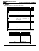
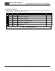
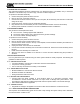
Function Display Description Reference
M E
M E
M E
M E
ME
ME
ME
ME
M E
M E
Use
or
keys to adjust to new set point
ME
M E
M E
ME
M E
ME
ME
Key
--0%LEL- Default Display
Mode ALMRSET: Mode Function - Alarm Reset
Mode CALIB:-- Mode Function - Calibrate
Mode SETUP:--- Mode Function - Set Point Adjustments
Enter Alarms S.P. Function - Alarm Adjust * A Below
Down Relays S.P. Function - Relays Adjust * B Below
Down Gas S.P. Function - Gas Type/Range Adjust * C Page 22
Down 4-20mA S.P. Function - 4-20 mA Adjust * D Page 22
Down RS-485 S.P. Function - RS-485/Sentry Output Adjust * E Page 22
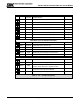
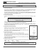
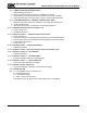
High Alarm Set Point Adjustment Example
Enter H.Alarm S.P. Function - High Alarm Adjust *A
Enter HASP:60- Alarm Set Point: current = 60
Down (x5) HASP:55- Alarm Set Point: new = 55
Enter ACK Momentary Acknowledge of new Set Point
H.Alarm S.P. Function - Alarm Adjust
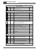
Relays Set Point Adjustment Example
Enter H. Relay S.P. Function - Alarm Relay Adjust *B
Down L.Relay S.P. Function - Warning Relay Adjust
Enter Latch
Use
or
keys to adjust to new relay action
(Latch, Sentry, NonLatc) * indicates current
Down Sentry
NOTE: Sentry indicates that Sentry controls relay
action and not the IT Sensor Module
Down *Sentry Alarm Relay set to Sentry
Table 5 - 3 A: Set-Up Configuration