
Instruction manual

Model 5100-02-IT Combustible Gas Sensor Module
Page: 20
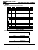
5.3 SET-UP
The sensor module set-points menu is used to initially set-up the alarm set points, relay actions, gas type and
range, 4-20 mA action and RS-485/Sentry address and baud rates (See Menu Key in Appendix J). When in
the SETUP screen use the [▲] or [▼] keys to select submenu and use [E] to enter.
Alarms: Use the [▲] or [▼] keys to select Low Alarm (Warning) or High Alarm (Alarm) menu. Key
[▲] will adjust the setpoint upwards and Key [▼] will adjust the value downwards. Once it reaches
the desired setpoint, Key [E] will accept it and ACK will appear. Set-points can be configured using
this menu to values between 0 and 60.
Relays: Use the [▲] or [▼] keys to select Low Alarm (Warning) or High Alarm (Alarm) relay menu
and press [E]. Use the [▲] or [▼] keys to select the correct alarm relay action for the application,
Latch, Sentry or Non-Latch. Selecting “Sentry” enables the Sentry controller to make all alarm
action decisions. * indicates the current selection.
Gas Factor: A calibration standard of Methane may be used in conjunction with scaling factors to
cause alarm function in %LEL scale of another gas. See Appendix I for a list of the scaling factors.
Note that if the 5100-02-IT is interfaced to a Sentry controller that the gas factor can be set in the
Sentry or the Gas Sensor Module but NOT IN BOTH. It is recommended that the gas factor be
adjusted in the Gas Sensor Module so that the display values on both the Gas Sensor Module and
the Sentry are matched. Note that gas factors are not applicable during calibration.
4-20mA: Use the [▲] or [▼] keys to select Calib, or CalibOut TblOut menu and press [E]. The
“Calib” section of the menu allows the user to calibrate the 4 mA and 20 mA outputs. To calibrate
the 4 mA and 20 mA outputs it is necessary to have an amp meter connected to the 5100-02-IT and
upon selecting the 4 mA output calibration then the [▲] or [▼] keys can be used to adjust the 4 mA
reading on the amp meter until it reads 4 mA. Similar steps can then be performed for the 20 mA
output. The CalibOut section allows the user to select the 4-20 mA output action desired during
calibration. * indicates the current selected value. Available selections include:
Track – the 4-20mA value tracks the calibration gas exposed to the gas sensor module
C2.5mA – the 4-20mA value is held at 2.5mA during calibration
C4.00mA – the 4-20mA value is held at 4.0mA during calibration.
The Tbl Out menu enables the user to select the mA output value for the Trouble Alarm. Select
“T1.5mA” to choose the 1.5mA default valve. Or select “User mA” and use the [▲] or [▼] keys to
select any valve between 0.5mA and 3.7mA.
RS-485 - Use the [▲] or [▼] keys to select Address or Baud rate menu and press [E]. Note that the
5100-02-IT has a rotary switch on the faceplate and it is used to select addresses 1-15. When
connected to Sentry the user can select 1-8 and using Modbus RS-485 the user can select
addresses 1-15. For Modbus addresses above 15, set the rotary switch to 0 and then use the
“Address” menu to select any address between 16 and 254. The Baud rate menu allows the user
to select a baud rate of 38400, 19200, 9600, 4800 or 2400. * indicates current selection.
RS485 default parameters are: 38,400 baud, 8 bits, 1 stop bit, no parity