
Instruction manual

Model 5100-02-IT Combustible Gas Sensor Module
Page: 19
5.2 MAIN MENU
Table 5-1 describes the primary human-machine interface operation.
Table 5-2 describes the operational display values of the human-machine interface system.
ID THE DISPLAY SHOWS “START” INSTEAD OF “STARTING, THE MODULE MUST BE CALIBRATED BEFORE USING IT.
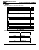
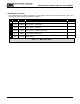
Table 5 - 1: Master Menu
Display Description
STARTING Warm-up at start-up
##%LEL Concentration
L ##%LEL Low Alarm (Warning)
H ##%LEL High Alarm (Alarm)
HIGH >100% Full Scale
NO SENSR Sensor Failure
C ##%LEL Calibration Mode
ACK Acknowledged Function
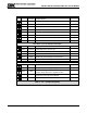
Table 5 - 2: Operation Display Values
Function Display Description Reference
M E
M E
ME
ME
M E
M E
M E
M E
M E
M E
M E
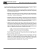
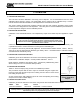
Key
Mode Switch [M]
Enter Switch [E]
Up Switch [▲] Previous Menu
Down Switch [▼] Next Menu
5100-02 First screen at power up-model
1.Xxa VX.Xxx Second screen at power up-version
Warm.XXX Third screen at start up-warm up
0%LEL Normal condition - default display
Mode ALMRSET: Mode Function -Alarms Acknowledge
SSSSSSSS
B
anner:
U
se <
M
> sw
i
tc
h
f
or
diff
erent menu
i
tems.
S
e
l
ect
<E> to enter menu item.
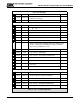
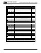
0%LEL Default Display
Mode ALMRSET: Mode Function - Alarms Reset
Mode CALIB: Mode Function - Calibrate Table 6-1
Mode SETUP: Mode Function - Module Set-up Table 5-3
Mode MAINT: Mode Function - Maintenance Table 5-4
Mode EXIT-? Exit Mode
Enter 0%LEL Apply Selected Mode (Exit)
0%LEL Default Display