
Instruction manual

Model 5100-02-IT Combustible Gas Sensor Module
Page: 13
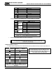
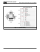
P3B PCB Label Function
1 P VDC Power
2 S Sentry Signal or Communication
3 G VDC Ground
P3A
4 P VDC Power
5 S Sentry Signal or Communication
6 G VDC Ground
P4 Connections are only available when the optional Relays are included
P4 PCB Label Function
1
WARN
N/C Low Alarm Relay NC
2 COM Low Alarm Relay COM
3 N/O Low Alarm Relay NO
4
ALARM
N/C High Alarm Relay NC
5 COM High Alarm Relay COM
6 N/O High Alarm Relay NO
7
TRBL
N/C Trouble Alarm Relay NC *
8 COM Trouble Alarm Relay COM*
9 N/O Trouble Alarm Relay NO*
* Trouble relay is fail safe so it is energized for normal operation,
functions are labeled for normal operation.
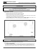
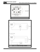
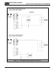
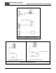
Table 4 - 2: Sensor Module External Interfaces
7. Establish the module address according to section 4.5.
NOTES
The starting delay period normally takes approximately 3 minutes but under some
circumstances can take longer.
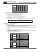
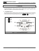
4.5 MODULE ADDRESS SWITCH
For digital interface applications the module address switch (or Modbus node) must be set per Table 4-2:
POSITION ADDRESS POSITION ADDRESS
NOTE
For Sentry applications only sensor addresses 1-8 are
allowed. If using Modbus output sensor addresses 1-15
are available. Position 0 allows the Modbus Address to be
set by software menu, in the range 16-254.
1 Sensor 1 9 Sensor 09
2 Sensor 2 A Sensor 10
3 Sensor 3 B Sensor 11
4 Sensor 4 C Sensor 12
5 Sensor 5 D Sensor 13
6 Sensor 6 E Sensor 14
7 Sensor 7 F Sensor 15
8 Sensor 8 0 Software Menu
Table 4 - 3: Sensor Module Address Switch
Positions