
Instruction manual

Model 5100-02-IT Combustible Gas Sensor Module
Page: 12
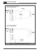
Prior to installation and wiring.
1. Remove the transmitter from the module housing by:
Unscrew the two captive panel screws in the face plate.
Lift the transmitter out of the enclosure housing.
Unplug the sensor cable from transmitter assembly connector J1.
Remove the sensor assembly from the enclosure hub.
2. Install the module housing onto the end of the supply conduit and/or bolt into position as required.
NOTES
When housing earth grounding is required for the installation a grounding lug is located in the
base of the enclosure. Install the earth ground wire under the green lug.
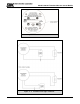
4.4 TRANSMITTER AND SENSOR INSTALLATION
When all pre-wire is complete:
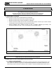
1. Install sensor assembly in the open hub on the module enclosure. The sensor assembly thread
must be fully seated into the hub and tightened to maintain explosion proof assembly.
2. Connect the sensor assembly cable to top transmitter board connector J1.
3. Align the headers between the top transmitter board and the lower termination board and push
together.
4. Turn rotary switch to correct sensor address if required.
5. Carefully return the transmitter to the enclosure installing it over the two stand-off’s. Tighten the
retaining screws into the stand-offs.
6. Cycle power to accept module address change.
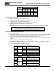
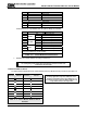
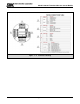
P1 PCB Label Function
1
Switch
IN + Digital Input SW +
2 IN - Digital Input SW -
3
4-20
IN + 4-20 mA Input +
4 IN - 4-20 mA Input -
5 GND Ground
6
4-20
OUT + 4-20 mA Output
7 OUT - 4-20 mA Output
P2 PCB Label Function
1
RS 485
+ RS 485 (+) (A)
2 - RS 485 (-) (B)
3 S RS 485 shield (Isolated GND)
4
RS 485
+ RS 485 (+) (A)
5 - RS 485 (-) (B)
6 S RS 485 shield (Isolated GND)
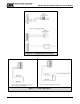
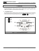
Number
of
modules
Maximum length of wire run (feet)
500 1,000 2,000 3,000 5,000
1
18 18 16 16 14
2
18 18 14 12 xx
3
18 16 12 xx xx
4
16 14 12 xx xx
Table 4 - 1: Minimum Wire Gauges