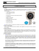
MODEL 5100-02-IT IT Series COMBUSTIBLE GAS SENSOR MODULE Version 3.00A APPLICABILITY & EFFECTIVITY Effective for all Model 5100-02-IT Modules manufactured after December 1, 2011. Instruction Manual Part Number T12019 Rev.
Model 5100-02-IT Combustible Gas Sensor Module FM APPROVAL ONLY THE FOLLOWING ITEMS, FUNCTIONS AND OPTIONS ARE FM* APPROVED Model 5100-02-IT Combustible Gas Sensor Module Sensor Module Model 5100-02-IT Combustible Gas Sensor Module Calibration Equipment Model 1200-26 Calibration Gas Delivery System Model 1290-02 Combustible Gas Cylinder Model 5358-01 Calibration Head, Standard Model 5360-00 Calibration Gas Delivery Fitting Model 1260-02 Combustible 50% LEL Gas Cylinder Model 1260-42 Cylinder
Model 5100-02-IT Combustible Gas Sensor Module TABLE OF CONTENTS 1. 1.1 1.2 1.3 1.4 1.5 1.6 1.7 2. 2.1 2.2 2.3 3. 3.1 3.2 3.3 3.4 3.5 4. 4.1 4.2 4.3 4.4 4.5 5. 5.1 5.2 5.3 5.4 6. 6.1 6.2 6.3 6.4 6.5 6.6 7. 7.1 7.2 7.3 7.4 7.5 PRODUCT DESCRIPTION ................................................................................................................................. 3 GENERAL .............................................................................................................................
Model 5100-02-IT Combustible Gas Sensor Module 8. 8.1 8.2 8.3 8.4 8.5 8.6 8.7 8.8 8.9 APPENDICES ................................................................................................................................................... 29 APPENDIX A: SPECIFICATIONS.................................................................................................................. 29 APPENDIX B: MODEL NUMBERS, PARTS LIST & PARAMETERS.............................................................
Model 5100-02-IT Combustible Gas Sensor Module 1. PRODUCT DESCRIPTION 1.1 GENERAL The Model 5100-02-IT Catalytic Bead Combustible Gas Sensor Module is a member of the Sentry Information Technology ”IT” family of gas sensor transmitter modules.
Model 5100-02-IT Combustible Gas Sensor Module 1.4.2 MODBUS OPERATION An RS-485 Modbus RTU serial interface allows direct connection to standard PLCs and DCSs. The Module Address Switch (section 4.5) allows the user to select up to 15 different Modbus addresses. Also, up to 254 different Modbus Addresses are available via menu selection. Figure 4-5 in this manual provides the wiring terminations for Modbus connections. 1.4.
Model 5100-02-IT Combustible Gas Sensor Module 1.6 INTERCONNECT WIRING Not supplied with the sensor module, but necessary to the installation and operation is the multi conductor wiring which connects the module to its power source and controller. Before this wiring is installed it is important to read and understand the control system installation instructions to determine wiring alternatives requirements and alternatives. 1.7 POWER REQUIREMENTS IT modules operate on DC power between 10 VDC and 30 VDC.
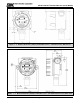
Model 5100-02-IT Combustible Gas Sensor Module Figure 1 - 2: Model 5100-02-IT-S1 (and S2) Combustible Sensor – 316SS Enclosures, Dimensions Figure 1 - 3: Model 5100-02-IT-A1 (and A2) Combustible Sensor – Cast Aluminum Enclosures, Dimensions Page: 6
Model 5100-02-IT Combustible Gas Sensor Module 2. CAUTIONS & WARNINGS 2.1 INTRODUCTION Although IT Transmitter Modules are designed and constructed for installation and operation in industrial applications including "hostile" environments, caution should be taken to insure that the installation is made in compliance with this instruction manual and that certain procedures and conditions are avoided. This chapter discusses the necessary cautions.
Model 5100-02-IT Combustible Gas Sensor Module Note that the 5100-02-IT has a gas factor scaling feature in which a calibration standard of Methane or Propane may be used in conjunction with scaling factors to cause alarm function in %LEL scale of another gas. See Appendix G.
Model 5100-02-IT Combustible Gas Sensor Module 3. QUICK START 3.1 OVERVIEW The gas sensor module has been supplied factory calibrated and ready for immediate installation and operation. An installer familiar with installation and operation of gas detection products can use this section to begin immediate use of the module. 3.2 WIRING See section 4.2 to determine if 3-wire or 4-wire operation is necessary. Provide twisted shielded wiring from the power supply/control device to the sensor module location.
Model 5100-02-IT Combustible Gas Sensor Module 4. INSTALLATION NOTE All IT modules are factory pre-configured and calibrated. All modules are tagged to indicate the configuration including the sensor module number Identify all components during unpacking and install using the factory configuration. 4.1 SENSOR MODULE LOCATIONS Select locations for each sensor modules based on the following: Modules should be placed close to the potential source of gas.
Model 5100-02-IT Combustible Gas Sensor Module cable shield must never be used as a conductor. Larger gauge wire is recommended with distances over 1000’. Connect wires as shown in figure 4-4. For a 4-Wire isolated connection, set jumpers, located on the bottom of the transmitter board, to the upper position as illustrated in Figure 4.4. Verify that both jumpers are in the position marked by 4-wire.
Model 5100-02-IT Combustible Gas Sensor Module Number of modules 500 1,000 2,000 3,000 5,000 1 18 18 16 16 14 2 18 18 14 12 xx 3 18 16 12 xx xx 4 16 14 12 xx xx Maximum length of wire run (feet) Table 4 - 1: Minimum Wire Gauges Prior to installation and wiring. 1. Remove the transmitter from the module housing by: Unscrew the two captive panel screws in the face plate. Lift the transmitter out of the enclosure housing.
Model 5100-02-IT Combustible Gas Sensor Module P3B 1 2 3 PCB Label P S G Function VDC Power Sentry Signal or Communication VDC Ground P3A 4 5 6 P S G VDC Power Sentry Signal or Communication VDC Ground P4 Connections are only available when the optional Relays are included P4 PCB Label Function 1 N/C Low Alarm Relay NC 2 COM Low Alarm Relay COM WARN 3 N/O Low Alarm Relay NO 4 N/C High Alarm Relay NC 5 COM High Alarm Relay COM ALARM 6 N/O High Alarm Relay NO 7 N/C Trouble Alarm Relay NC * 8 COM Troubl
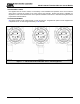
Model 5100-02-IT Combustible Gas Sensor Module Figure 4 - 2: Transmitter Face Plate Figure 4 - 3: 4-20 mA Circuits Types 5100-02-IT Page: 14
Model 5100-02-IT Combustible Gas Sensor Module (DEFAULT) Figure 4 - 4: 4-20 mA Circuits Types 5100-02-IT – Connections Page: 15
Model 5100-02-IT Combustible Gas Sensor Module + - Figure 4 - 5: Digital Interface Connections Figure 4 - 6: Remote Alarm Reset Page: 16
Model 5100-02-IT Combustible Gas Sensor Module Figure 4 - 7: Termination Drawing Page: 17
Model 5100-02-IT Combustible Gas Sensor Module 5. OPERATION The Combustible Gas Sensor utilizes a visual menu system operated by means of a magnet. A magnet stick is supplied for this purpose. The menu system is used to configure alarm set-points, calibrate the sensor module, and for maintenance procedures and alarms acknowledge. 5.1 DATA ENTRY KEY PAD The module menu system is operated by means of directing the magnet stick toward each of four independent hall-effect magnetic switches.
Model 5100-02-IT Combustible Gas Sensor Module 5.2 MAIN MENU Table 5-1 describes the primary human-machine interface operation. Key Function M M M M E E E E Switch [M] Enter Switch [E] Up Down Mode Switch [▼] Next Menu 5100-02 First screen at power up-model VX.Xxx Second screen at power up-version Warm.
Model 5100-02-IT Combustible Gas Sensor Module 5.3 SET-UP The sensor module set-points menu is used to initially set-up the alarm set points, relay actions, gas type and range, 4-20 mA action and RS-485/Sentry address and baud rates (See Menu Key in Appendix J). When in the SETUP screen use the [▲] or [▼] keys to select submenu and use [E] to enter. Alarms: Use the [▲] or [▼] keys to select Low Alarm (Warning) or High Alarm (Alarm) menu.
Model 5100-02-IT Combustible Gas Sensor Module Key Function Display --0%LEL- M M M M M M M M E E E E E E E E Description Reference Default Display Mode ALMRSET: Mode Function - Alarm Reset Mode CALIB:-- Mode SETUP:--- Enter Alarms S.P. Function - Alarm Adjust * A Below Down Relays S.P. Function - Relays Adjust * B Below Down Gas S.P. Function - Gas Type/Range Adjust * C Page 22 Down 4-20mA S.P.
Model 5100-02-IT Combustible Gas Sensor Module Gas Factor Example M E M E M E Enter GasFactr S.P. Function - Gas Factor Adjust Enter Factr100 Select [E] to select or or to adjust factor number and press [E] Enter ACK *C Acknowledgement of new Gas Factor Value 4-20 mA Adjustment Example M M M M M M M E E E E E E E Enter Calib S.P.
Model 5100-02-IT Combustible Gas Sensor Module 5.4 MAINTENANCE FUNCTIONS The maintenance menu allows the operator to verify module firmware version and configuration code. The maintenance menu operation is described in Table 5-4.
Model 5100-02-IT Combustible Gas Sensor Module 6. CALIBRATION 6.1 CALIBRATION FREQUENCY The 5100-02-IT has been calibrated in the factory prior to shipment. It is recommended that the user check calibration before placing in service. The Combustible sensor module must be calibrated every 6 months. Periodic functional tests are advisable for critical applications and hostile environments.
Model 5100-02-IT Combustible Gas Sensor Module 6.6 CALIBRATION SUB-MENU Key Function Display --0%LEL- M M M E E E M E Mode ALMRSET: Mode CALIB:-- Enter CAL-0%-- M E Reference Default Display Mode Function - Alarm Reset Mode Function - Calibrate Banner: Apply zero gas, enter when done Operation: Confirm area clear of gas, or apply zero air to sensor.
Model 5100-02-IT Combustible Gas Sensor Module 7. SERVICE 7.1 MODULE SUB ASSEMBLY Figure 7 - 1: Module Components NOTE Area must be determined to be non-hazardous before opening enclosure. 7.2 ENCLOSURE REPLACEMENT The enclosure should be replaced if the cover threads or conduit threads have been damaged, or if the enclosure has been damaged sufficiently that it no longer meets the required NEMA classification.
Model 5100-02-IT Combustible Gas Sensor Module 7.3 TRANSMITTER REPLACEMENT The transmitter assembly should be replaced when it is determined that it is unreliable, noisy or cannot be calibrated. This situation may occur due to age, corrosion or failed components. To replace the transmitter assembly: a. Confirm that system power has been removed. b. Remove the cover of the main enclosure. c.
Model 5100-02-IT Combustible Gas Sensor Module 7.5.3 1. 2. 3. 4. 7.5.4 IF MODULE DOES NOT RESPOND TO GAS Repeat calibration procedure. Remove the gas and wait for the timer to completely count down. Apply 50%LEL and verify that the sensor sees 50% LEL gas after calibration. If the sensor still does not see gas, power cycle the unit and repeat calibration. IF THE MODULE DISPLAYS “STARTING” FOR MORE THAN 1 HOUR 1. Make sure the sensor is placed in an ambient room temperature environment. 2.
Model 5100-02-IT Combustible Gas Sensor Module 8. APPENDICES 8.1 APPENDIX A: SPECIFICATIONS Sensor: Type: Range: Repeatability: Response time: Accuracy: Sensor Life: Catalytic Bead 0-100% LEL Combustible +/-1% LEL < 12 sec to 60% full scale +/- 1% for 0-50% LEL range +/- 2% for 51-100% LEL range Typically >3 years Output: Display: Relays Option: Signal Output: Fixed and Scrolling LED Trouble (SPDT Form C, 0.
Model 5100-02-IT Combustible Gas Sensor Module Baud: Parity: Stop bit: Data bits: Flow Control: Memory map: 38400 (Adjustable 2400 to 38400 baud) None 1 8 None Appendix H Limited warranty: 2 years Warranty: Specifications subject to change without notice 8.2 APPENDIX B: MODEL NUMBERS, PARTS LIST & PARAMETERS Model 5100-02-IT Sensor Module Enclosure - XX - A1 = AL ¾” NPT - A2 = AL M20 x 1.5 - S1 = SS ¾” NPT - S2 = SS M20 x 1.
Model 5100-02-IT Combustible Gas Sensor Module 8.3 APPENDIX C: LIMITED WARRANTY SIERRA MONITOR CORPORATION warrants its products to be free from defects in workmanship or material under normal use and service for two years after date of shipment. SMC will repair or replace without charge any equipment found to be defective during the warranty period. Final determination of the nature and responsibility for defective or damaged equipment will be made by SMC personnel.
Model 5100-02-IT Combustible Gas Sensor Module 8.4 APPENDIX D: REMOTE SENSOR OPTION Figure 8 - 1: Remote Sensor Option NOTE: Drawing using Stainless Steel enclosure available from Sierra Monitor.
Model 5100-02-IT Combustible Gas Sensor Module Setting Up and Testing Model 5100-02-IT with Remote Sensor 1. Connect the remote module (p/n 5394-51) to Model 5100-02-IT. 2. Power up Model 5100-02-IT. 3. Connect the voltmeter from pin 4 to pin 3 of the connector (p/n 59201) (at the side connected to the sensor). 4. Verify the voltage from pin 4 to pin 3 is 2 volts.
Model 5100-02-IT Combustible Gas Sensor Module 8.
Model 5100-02-IT Combustible Gas Sensor Module Figure 8 - 3: 4-20 mA Circuits Types 5100-02-IT – Connections - HART Page: 35
Model 5100-02-IT Combustible Gas Sensor Module HART PROTOCOL MENU HART (Highway Addressable Remote Transducer) Protocol is the global standard for sending and receiving digital information across analog wires between smart devices and control or monitoring system. HART is a bi-directional communication protocol that provides data access between intelligent field instruments and host systems.
Model 5100-02-IT Combustible Gas Sensor Module Device Specific Commands Summary Command Number 130 131 132 133 134 135 136 137 138 139 140 141 142 143 144 145 146 147 148 149 150 Description Key Press Set Alarm Level Set Warning Level Set Alarm Relay Action Set Warning Relay Action Reset Alarms Abort Calibration Set Calibration Gas Level Apply ZERO Gas Apply SPAN Gas RESERVED Force Gas Value Reset Force Gas Value Read MODBUS RTU Register Set Transducer Serial Number Set Calibration Mode output current Set
Model 5100-02-IT Combustible Gas Sensor Module Command Specific Response Data Bytes: Byte 0 Format Unsigned‐8 Description Returns new Alarm Level. Format Unsigned‐8 Description Warning level, range 0 to 60. Default is 20. Command 132: Set Warning Level Request Data Bytes: Byte 0 Command Specific Response Data Bytes: Byte 0 Format Unsigned‐8 Description Returns new Warning Level.
Model 5100-02-IT Combustible Gas Sensor Module Command 137: Set Calibration Gas Level Request Data Bytes: Byte 0 Format Unsigned‐8 Description Calibration Gas Level, range 0 to 100 Command Specific Response Data Bytes: Byte 0 Format Unsigned‐8 Description Returns new Calibration Gas Level Command 138: Apply ZERO Gas This command will signal the module to accept the present sensor output to as the ZERO gas condition.
Model 5100-02-IT Combustible Gas Sensor Module Command Specific Response Data Bytes: Byte 0‐1 Format Unsigned‐16 Description Returns contents of selected Modbus Register Command 144: Set Transducer Serial Number This command allows user to add a device specific serial number, if required. This is different from the serial number assigned by the Manufacturer.
Model 5100-02-IT Combustible Gas Sensor Module Command Specific Response Data Bytes Byte Format 0 Unsigned‐8 Description Returns new Gas Factor value Command 150: Write MODBUS RTU Register This command allows the writing of sensor module data as defined in the MODBUS RTU register map.
Model 5100-02-IT Combustible Gas Sensor Module 8.
Model 5100-02-IT Combustible Gas Sensor Module 8.
Model 5100-02-IT Combustible Gas Sensor Module 8.
Model 5100-02-IT Combustible Gas Sensor Module Page: 45
Model 5100-02-IT Combustible Gas Sensor Module 8.
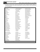
Model 5100-02-IT Combustible Gas Sensor Module INDEX 4-20 MA ........................................................3, 20, 22 MODULE.............................................................. 7, 9 ALARMS ...........................................................20, 44 MODULE ADDRESS SWITCH .............................. 13 ANALOG ................................................................... 4 OPTIONS ............................................................... 30 CALIBRATION ...........