
Instruction manual


Model 4101-28/5100-28 IR Gas Sensor Module (7/03)
Page:
Instruction Manual
5
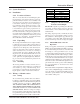
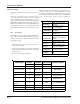
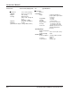
eludoM snoitisoPhctiwS
#123
1NONONO
2FFONONO
3NOFFONO
4FFOFFONO
5NONOFFO
6FFONOFFO
7NOFFOFFO
8FFOFFOFFO
6. When the wiring , module number, and the voltage
have been verified, gently plug in the control module.
7. The display will show Start delay Model 5100-28
Sierra Monitor.
8.Verify Sentry recognizes the desired module.
9.Calibrate 5100-28 gas sensor module.
2.3 Wiring and System Installation - Model
5000 Application
Refer to Sentry Gas Monitoring System, Ver. 6.0 In-
struction Manual.
2.3.1 Wiring
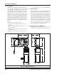
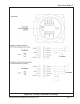
Caution: To access the wiring connections on the
5100-28, you will need to remove the enclosure cover
and then remove the cover plate. To remove the cover
plate, pull gently using the knob in the center of the
board.
1. See Table 1 for wire gauge recommendations.
2. Connect P (1) from Sentry channel to the terminal
at the right hand side which is labelled 24VDC
(position #1).
3.Connect G (3) from Sentry channel to the terminal
at the right hand side which is labelled
COMMON(position #2).
4.Connect S (2) from Sentry channel to the terminal
at the right hand side which is label Sentry (position
# 5).
5.Set the dip switch on each module to indicate the
module number. Each of the modules connected to
one controller must have a different address.
Note: Switch position 4 is not used