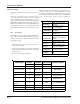
Model 4101-28/5100-28 IR Gas Sensor Module APPLICABILITY & EFFECTIVITY This manual provides instructions for the following Sierra Monitor products: Model 4101-28 5100-28 Description IR Gas Sensor Module (4-20 mA output) IR Gas Sensor Module (Sentry bus output) The instructions are effective for the above models as of October 2002 Instruction Manual Part Number T12013 Rev.
Table of Contents 1.0 Description ................................................................................................................................................................. 1.1 How It Works ......................................................................................................................................................... 1.2 Sensors Poisons and Inhibitors ..............................................................................................................
Instruction Manual 1.0 Description The IR Gas Sensor Module utilizes Infrared technology to monitor for combustible gases over the range of 0-100% LEL. The IR Gas Sensor Module requires minimal maintenance with a calibration check once a year. Internal continuous self-diagnostics will automatically indicate any fault or optics problems. The IR Gas Sensor Module has both digital signal (510028) and a 4-20 mA output signal (4101-28).
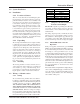
Instruction Manual 2.0 System Installation 2.1 Installation 2.1.1 Location of Sensors There are no absolute rules for determining the quantity and location of gas detection heads to protect any particular facility. Locate the sensors carefully in all areas where gas escape may be expected and where it is desirable to detect the presence of unwanted gas. Use redundancy where enhanced protection or reliability is required.
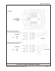
Instruction Manual 2.2.4 Sensor Life Note: The 4101-28's to 20 mA current output must be conSensor life of the module can be expected to exceed 5 nected to a load device in order to facilitate the use of the test jacks (ie. 100 Ohm resistor must be connected between years. the 4 to 20 mA signal output and the common terminal if the Sensor response may deteriorate very slowly over a pe- unit is being bench tested to field installation). riod of years, depending on exposure to environmental factors.
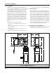
Instruction Manual Figure 2.
Instruction Manual 2.3 Wiring and System Installation - Model 5000 Application Refer to Sentry Gas Monitoring System, Ver. 6.0 Instruction Manual. 2.3.1 Wiring Caution: To access the wiring connections on the 5100-28, you will need to remove the enclosure cover and then remove the cover plate. To remove the cover plate, pull gently using the knob in the center of the board. 6. When the wiring , module number, and the voltage have been verified, gently plug in the control module. 7.
Instruction Manual 3.0 Calibration 3.1 Overview All applications require an initial calibration upon power up and before putting the modules into service. This initial calibration is considered a local calibration, begun and completed at the module. In the Sentry applications, the initial local calibration is to be followed up with a global calibration at the controller. (See Chapter 5 in the Sentry manual, T121001).
Instruction Manual Construction: 5100-28 Sentry Display Bus 13.5 x 4.75 x 4.2 inches (34.3 x 12.1 x 10.7 cm) 5 lb. (2.2 Kg) Explosion proof, Class 1, Div. I, Groups B, C, D CSA Class 1, DIN I, Groups B, C, D NRTL/C Appovals 2 years Warranty: (Specifications subject to change without notice) Dimensions: (HxWxD) Weight: Housing: 4.
Instruction Manual 5.0 Limited Warranty SIERRA MONITOR CORPORATION warrants its products to be free from defects in workmanship or material under normal use and service for two years after date of shipment. SMC will repair or replace without charge any equipment found to be defective during the warranty period. Final determination of the nature and responsibility for defective or damaged equipment will be made by SMC personnel.