
Instruction manual


Model 5100-99-IT 4-20 mA Transmitter
Page: 2
1.3.2
e additional terminal connectors to enable the user to connect In/Out terminations of
1.3.3
3 (3-wire) or Type 4 (4-wire) circuit as described by ANSI/ISA-
1.3.4
is only resets local alarms, not Sentry alarms. This
operated in a supervised mode that both the switch and resistor
Figure 3-7.
1.3.5
VAC, 8 Amps for the High
ys, it will include Terminal P4 on the interface board
elay output connections are on P4.
1.3.6
of comprised of the following three primary components:
1.3.7
viewing window. The design of the enclosures allows 3-way mounting
hoices as shown in figure 1-3.
MODBUS OPERATION
An RS-485 Modbus RTU serial interface allows direct connection to standard PLCs and DCSs. The
Transmitter Address Switch (section 3.5) allows the user to select up to 16 different Modbus addresses.
Also, an additional 238 Modbus addresses (for a total of 254 different Modbus Addresses) are available
via menu selection. Figure 3-6 in this manual provides the wiring terminations for Modbus connections. The
5100-XX-IT provides th
a RS-485 connection.
ANALOG OPERATION
The 4-20 mA interface allows direct connection to standard analog controllers or PLCs. The 5100-XX-IT 4-
20 mA connection can be wired as a Type
50.00.01-1975 Standard (see figure 3-5).
REMOTE ALARM RESET (DIGITAL INPUT) (Figure 3-7)
An input is available for connection of remote alarm reset/acknowledge. Figure 3-7 provides the wiring
termination for connecting the remote alarm reset. Th
input can be wired as supervised or non-supervised.
Note that when the Remote Alarm Reset is
must be present as outlined in
OPTIONAL INTEGRAL RELAYS
The optional relays are integral to the transmitter and are rated as SPDT, 250
Alarm and Low Alarm relays and SPDT, 250 VAC, 2 Amp for the Trouble relay.
If the transmitter is provided with the optional rela
(Figure 3-2). R
MECHANICAL
The transmitter
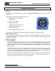
ENCLOSURE
Standard on the 5100-99-IT-AL is an explosion-proof, rain-tight cast aluminum electrical housing (Figure 1-
1) with three ¾” FNPT conduit hubs. The 5100-99-IT-SS (Figure 1-2) has a 316 Stainless Steel enclosure.
oth enclosure covers have a B
c