
Instruction manual

Model 5100-99-IT 4-20 mA Module
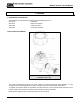
6.3 TRANSMITTER REPLACEMENT
The transmitter assembly should be replaced when it is determined that it is unreliable, noisy or cannot be
adjusted for calibration. This may occur due to age, corrosion or failed components.
To replace the transmitter assembly:
a. Remove the cover of the main enclosure
b. Unscrew the two thumb screws in the top of the cover plate, lift the assembly and rotate 90
o
to relieve the
wiring service loop
c. Unplug the sensor connector from the transmitter
d. Plug connector into new transmitter (be sure to match numbers between connector and socket).
e. Restore power and allow a minimum of 3 hours for stabilization before re-calibration
6.4 INSTALLATION INSPECTION
Prior to system start-up or trouble shooting the entire system should be visually inspected. The following are
guidelines for that inspection:
6.4.1.1 CONTROLLER INSTALLATION
• Controller installed in conformance to instruction manual recommendations.
• AC power is correctly grounded.
• Hot AC and relay connections have safety covers installed.
6.4.1.2 MOISTURE TRAPS AND RAINSHIELDS
• Conduit seals and drains installed to avoid moisture build up in electronics enclosure. Water
accumulation in transmitter enclosures is a major cause of damage and system failures - take
precautions to seal electrical conduits and provide moisture traps and drains to avoid water damage
• Rain-shields installed where applicable.
6.4.1.3 STANDARD VOLTAGES
• DC Voltage to be applied to the transmitter must be between 10 VDC and 30 VDC.
6.5 INSPECTION AND TROUBLESHOOTING GUIDE
This inspection and troubleshooting guide can be used to step through the system start-up and to determine
the corrective action if a fault occurs.
6.5.1.1 IF TRANSMITTER DOES NOT RESPOND TO GAS
1. Repeat calibration procedure.
2. Remove the gas and wait for the timer to completely count down.
3. Apply calibration gas and verify that the sensor sees calibration gas after calibration.
4. If the sensor still does not see gas, power cycle the unit and repeat calibration.
6.5.1.2 IF THE TRANSMITTER DISPLAYS “STARTING” FOR MORE THAN 1 HOUR
1. Make sure the sensor is placed in an ambient room temperature environment.
2. Power cycle the sensor.
3. Ensure that the sensor is not exposed to the gas of interest during warm-up.
6.5.1.3 IF THE TRANSMITTER DOES NOT DISPLAY THE CORRECT PPM
1. Power cycle the unit
2. Recalibrate the sensor.
6.5.1.4 IF THE DISPLAY SHOWS ‘F’
1. Power down the unit
2. Open the enclosure and unplug the sensor assembly from the transmitter board.
3. Plug the sensor back into the transmitter board carefully and ensure a secure fit.
4. Power up the unit.
6.5.1.5 IF THE DISPLAY SHOWS ‘C’
1. Complete calibration and exit to operating mode.
6.5.1.6 IF THE DISPLAY SHOWS ‘S’
1. Check connections with Sentry Connections.
Page: 24