
Instruction manual


Model 5100-99-IT 4-20 mA Module
5. CALIBRATION
5.1 CALIBRATION FREQUENCY
The 5100-99-IT has been calibrated in the factory prior to shipment. It is recommended that the user check
calibration before placing in service. Periodic functional tests are advisable for critical applications and hostile
environments.
The transmitter microprocessor software includes high level self checking algorithms which provide continuous
diagnostic and self adjustment. Users may select calibration frequencies dependent upon sensor type.
5.2 CALIBRATION PREPARATION
Calibration of the transmitter with sensor is accomplished by simple menu based steps and application of span
gas.
NOTE
If an error is made during any stage of the calibration process, hold the magnet stick at the
Switch [M] for 10 seconds. A scrolling display will indicate “Calibration aborted” and the
sensor module will exit the calibration activity and return to normal operating mode. The
calibration procedure can then be restarted.
Calibration must be performed only when the area is known to be clear of the applicable toxic gas. If
necessary, use a portable instrument to confirm that there is no background toxic gas.
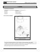
Figure 5-1
Model 5358-00 Calibration
Adapter
5.2.1 CALIBRATION GAS DELIVERY METHODS
Calibration gas is can be delivered to the sensors via the following delivery devices:
Model 5358-00: Calibration Adapter - used with portable calibrators. See 5-1.
Model 5360-00: Calibration Gas Delivery fitting - permanently installed fitting which
allows tubing to be run to a convenient delivery location
5.3 CALIBRATION PROCEDURE
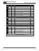
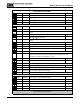
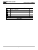
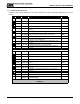
Table 5-1 shows the step by step process of the calibration procedure.
The procedures requires that the menu “keys” be activated using the magnet stick.
Each key pressed steps through the process of setting the zero value for clean air
and then setting the span value.
At each of these steps, apply calibration gas of the value corresponding to the
setting accepted on the sensor module display.
Page: 21