
Instruction manual

Model 5100-99-IT 4-20 mA Transmitter
Page: 16
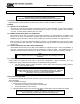
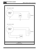
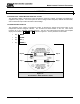
4.3 MAIN MENU
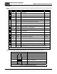
Table 4-1 describes the primary man-machine interface operation (The blackened box is the selected menu
function).
Function Display Description Reference
M E
ST
M E
ST
ME
S T
ME
S T
M E
ST
M E
ST
M E
ST
M E
ST
M E
ST
M E
ST
M E
ST
M E
ST
XXX PPM Default Display
(Once a minute the sensor displays module address)
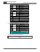
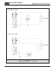
Table 4-1 Master Menu
Enter XXX PPM Apply Selected Mode (Exit)
Mode EXIT-?-- Exit Menu
Mode MAINT:-- Mode Function - Maintenance Table 4-4
Mode SETUP:-- Mode Function - Set Point Adjustments Table 4-3
Mode CALIB:-- Mode Function - Calibrate Table 5-1
Mode ALMRSET: Mode Function - Alarm Reset
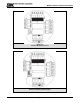
XXX PPM Default Display
RESET Alarm Reset
Banner: "Press [E] to reset alarm"
Mode ALMRSET: Mode Function - Alarm Reset
XXX PPM Normal condition - default display
START XX Third screen at start up: Start Count Up
VXX-XX-- Second screen at power up: Version No.
5100-99 First screen at power up: Model No.
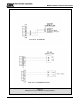
Down Switch [▼] Next Menu
Up Switch [▲] Previous Menu
Enter Switch [E]
Key
Mode Switch [M]
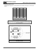
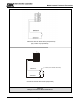
Table 4-2 describes the operational display values of the human-machine interface system.
DISPLAY DESCRIPTION
START
Delay from loss of power at start-up
XXX PPM
Concentration
LXXX PPM
Low Alarm
HXXX PPM
High Alarm
Measures gas, concentration exceeds
100% of Full Scale
CXXX PPM
Calibration Mode
Acknowledged Function
Table 4-2 Operation Display Values