
Instruction manual

Model 5100-99-IT 4-20 mA Transmitter
Page: 9
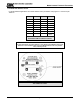
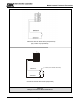
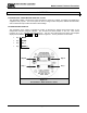
3.4 TRANSMITTER ADDRESS SWITCH
For digital interface applications the module address switch (or Modbus node) Figure 3-1 must be set per
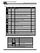
Table 3-2:
POSITION ADDRESS POSITION ADDRESS
1 Sensor 1 9 Sensor 09
2 Sensor 2 A Sensor 10
3 Sensor 3 B Sensor 11
4 Sensor 4 C Sensor 12
5 Sensor 5 D Sensor 13
6 Sensor 6 E Sensor 14
7 Sensor 7 F Sensor 15
8 Sensor 8 0 Software
Menu
Table 3-2
Transmitter Address Switch Positions
NOTES
For Sentry applications only sensor addresses 1-8 are allowed. If using Modbus output sensor
addresses 1-15 are available. Position 0 allows the Modbus Address to be set by software
menu, in the range 16-254.
Figure 3-1
Transmitter Face Plate