MODEL 5100-99-IT IT Series 4-20 mA Transmitter Version 2.
Model 5100-99-IT 4-20 mA Transmitter THIS PAGE IS INTENTIONALLY LEFT BLANK Contents
Model 5100-99-IT 4-20 mA Transmitter TABLE OF CONTENTS 1. PRODUCT DESCRIPTION .............................................................................................................................1 1.1 1.2 1.3 GENERAL........................................................................................................................................................1 PRODUCT CONFIGURATION..............................................................................................................
Model 5100-99-IT 4-20 mA Transmitter 6.5.4 7. IF THE TRANSMITTER DISPLAYS “STARTING” FOR MORE THAN 1 HOUR...................................24 APPENDICES ...............................................................................................................................................25 APPENDIX A: SPECIFICATIONS ............................................................................................................................25 APPENDIX B: MODEL NUMBERS & PARTS LIST ................
Model 5100-99-IT 4-20 mA Transmitter 1. PRODUCT DESCRIPTION 1.1 GENERAL The Model 5100-99-IT Transmitter is a member of the Information Technology “IT” family of gas sensor transmitters.
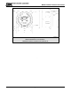
Model 5100-99-IT 4-20 mA Transmitter 1.3.2 MODBUS OPERATION An RS-485 Modbus RTU serial interface allows direct connection to standard PLCs and DCSs. The Transmitter Address Switch (section 3.5) allows the user to select up to 16 different Modbus addresses. Also, an additional 238 Modbus addresses (for a total of 254 different Modbus Addresses) are available via menu selection. Figure 3-6 in this manual provides the wiring terminations for Modbus connections.
Model 5100-99-IT 4-20 mA Transmitter Figure 1-1 Model 5100-99-IT-AL & SS Transmitter – Aluminum & Stainless Steel Enclosure, Dimensions .
Model 5100-99-IT 4-20 mA Transmitter Figure 1-3 Model 5100-99-IT Transmitter – Mounting Options 1.3.8 TRANSMITTER ELECTRONICS Electronic Assembly consist of one top transmitter board (connected to the cover plate) and a lower interface board. Connectors for wiring for power, signal interface and alarm relays are located on the interface board assembly 1.
Model 5100-99-IT 4-20 mA Transmitter 2. CAUTIONS & WARNINGS 2.1 INTRODUCTION Although IT Transmitter is designed and constructed for installation and operation in industrial applications including "hostile" environments, caution should be taken to insure that the installation is made in compliance with this instruction manual and that certain procedures and conditions are avoided. This chapter discusses the necessary cautions. Read the entire chapter prior to installation of the equipment. 2.
Model 5100-99-IT 4-20 mA Transmitter THIS PAGE INTENTIONALLY LEFT BLANK Page: 6
Model 5100-99-IT 4-20 mA Transmitter 3. INSTALLATION NOTE All transmitters are factory are pre-configured and calibrated. Identify all components during unpacking and install using the factory configuration. 3.1 TRANSMITTER LOCATIONS Select locations for each transmitter so that they are placed in areas accessible for calibration. 3.2 WIRING 3.2.1 ANALOG 4-20 mA OPERATION The 4-20 mA output for the 5100-99-IT can be either 3-wire or 4-wire operation.
Model 5100-99-IT 4-20 mA Transmitter P1 1 2 3 4 5 6 7 PCB Label Switch IN + IN 4-20 IN + IN GND 4-20 OUT + OUT - Function Digital Input SW + Digital Input SW 4-20 mA Input + 4-20 mA Input Ground 4-20 mA Output + 4-20 mA Output - P2 1 2 3 4 5 6 PCB Label Function RS 485 (+) (A) RS 485 (-) (B) RS 485 shield (Isolated GND) RS 485 (+) (A) RS 485 (-) (B) RS 485 shield (Isolated GND) P3B 1 2 3 P3A 4 5 6 PCB Label P S G Function VDC Power Sentry Signal or Communication VDC Ground P S G VDC Power Sentry S
Model 5100-99-IT 4-20 mA Transmitter 3.
Model 5100-99-IT 4-20 mA Transmitter Figure 3-2 Interface Board Connectors Figure 3-3 RS-485: Termination, BIAS Jumper Page: 10
Model 5100-99-IT 4-20 mA Transmitter Figure 3-4 4-20mA Circuit Types Page: 11
Model 5100-99-IT 4-20 mA Transmitter Figure 3-5 4-20mA Circuit Type Connections for 5100-99-IT Page: 12
Model 5100-99-IT 4-20 mA Transmitter 5100-99-IT TO SENTRY 5100-99-IT TO MODBUS DEVICE Figure 3-6 Wiring Connections for Modbus and Sentry Interface Page: 13
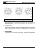
Model 5100-99-IT 4-20 mA Transmitter 5100-99-IT Remote Alarm Reset (Unsupervised) (Dry contact only unpowered) - OUT + - IN - + + IN SWITCH 4-20 GND 4-20 P1 4.
Model 5100-99-IT 4-20 mA Transmitter 4. OPERATION 4.1 INTRODUCTION – HUMAN-MACHINE INTERFACE SYSTEM The transmitter utilizes a visual menu system operated by means of a magnet. A magnetic tool (5358-50) is supplied for this purpose. The menu system is used to configure alarm set-points, calibrate the transmitter, and for maintenance procedures and alarms acknowledge. 4.
Model 5100-99-IT 4-20 mA Transmitter 4.3 MAIN MENU Table 4-1 describes the primary man-machine interface operation (The blackened box is the selected menu function). Key Function M S M S M S M S E T E T E T E T Display Description Mode Switch [M] Enter Switch [E] Up Switch [▲] Previous Menu Down Switch [▼] Next Menu 5100-99 M E S T Mode Reference First screen at power up: Model No. VXX-XX-- Second screen at power up: Version No.
Model 5100-99-IT 4-20 mA Module 4.4 CONFIGURE SET-POINTS The transmitter set-points menu is used to initially set-up the alarm set points, relay actions, range, 4-20 mA action and RS-485/Sentry address and baud rates. • Alarm Set-points: Once the Set-up menu is selected, press [E] to activate the Alarm Set-point screen. Use the [▲] or [▼] keys to select Low Alarm or High Alarm menu. Key [▲] will adjust the setpoint upwards and Key [▼] will adjust the value downwards.
Model 5100-99-IT 4-20 mA Module Key Function Display --0%LEL- M S M S M S M S M S M S M S M S E T E T E T E T E T E T E T E T M S M S E T E T M S M S E Down (x5) T E Enter T Description Reference Default Display Mode ALMRSET: Mode Function - Alarm Reset Mode CALIB:-- Mode SETUP:--- Enter Alarms S.P. Function - Alarm Adjust * A Below Down Relays S.P. Function - Relays Adjust * B Below Down Relays S.P. Function - Range Adjust * Page 19 Down 4-20mA S.P.
Model 5100-99-IT 4-20 mA Module Range Adjustment Example M S M S M S M S M S E T E T E T E T E T M S M S E T E T M S M S E T E T M S M S M S M S M S E T E T E T E T E T Enter Range Enter *100 PPM Down 10 PPM Down USER Enter 100 PPM S.P.
Model 5100-99-IT 4-20 mA Module 4.5 MAINTENANCE FUNCTIONS The maintenance menu enables the operator to view sensor and software versions. Sierra Monitor technical support has access to other values as needed. The maintenance menu operation is described in Table 4-4.
Model 5100-99-IT 4-20 mA Module 5. CALIBRATION 5.1 CALIBRATION FREQUENCY The 5100-99-IT has been calibrated in the factory prior to shipment. It is recommended that the user check calibration before placing in service. Periodic functional tests are advisable for critical applications and hostile environments. The transmitter microprocessor software includes high level self checking algorithms which provide continuous diagnostic and self adjustment.
Model 5100-99-IT 4-20 mA Module 5.3.1 SENSOR EXPOSURE TO GAS Calibration gas must be delivered to the sensor using the flow rate and duration specified by the sensor manual.
Model 5100-99-IT 4-20 mA Module 6. SERVICE 6.1 TRANSMITTER CONFIGURATION The transmitter is comprised of the following sub-assemblies (Figure 6-1): 5100-99-IT Transmitter SPL21810 Aluminum Enclosure SPL21823 316SS Enclosure SPL21824 Transmitter Assembly 6.
Model 5100-99-IT 4-20 mA Module 6.3 TRANSMITTER REPLACEMENT The transmitter assembly should be replaced when it is determined that it is unreliable, noisy or cannot be adjusted for calibration. This may occur due to age, corrosion or failed components. To replace the transmitter assembly: a. Remove the cover of the main enclosure b. Unscrew the two thumb screws in the top of the cover plate, lift the assembly and rotate 90o to relieve the wiring service loop c.
Model 5100-99-IT 4-20 mA Module 7. APPENDICES APPENDIX A - SPECIFICATIONS Output: Display: Relays (Optional): Analog Output (Optional) Signal Output: Fixed and Scrolling LED 8 Amp, High Alarm, Low Alarm, 2 Amp Trouble all SPDT Analog 4-20 mA (Trouble 0 mA, Calibration 1.
Model 5100-99-IT 4-20 mA Module APPENDIX B: - MODEL NUMBERS & PARTS LIST Transmitter 5100-99-IT-AL-01 5100-99-IT-AL-02 5100-99-IT-SS-01 5100-99-IT-SS-02 4-20 mA Transmitter, AL 4-20 mA Transmitter, Relay, AL 4-20 mA Transmitter, SS 4-20 mA Transmitter, Relay, SS Spare Parts SPL21824 SPL21810 SPL21823 SPL21825 SPL21829 Transmitter Enclosure, Transmitter, Aluminum Enclosure Transmitter, 316SS Interface Board without Relay Interface Board with Relay Page: 26
Model 5100-99-IT 4-20 mA Module APPENDIX C: LIMITED WARRANTY SIERRA MONITOR CORPORATION warrants its products to be free from defects in workmanship or material under normal use and service for two years after date of shipment. SMC will repair or replace without charge any equipment found to be defective during the warranty period. Final determination of the nature and responsibility for defective or damaged equipment will be made by SMC personnel.
Model 5100-99-IT 4-20 mA Module APPENDIX D: MODBUS MEMORY MAP Read Register Table Register 40001 40002 40003 40004 40005 40006 40007 40008 40009 40010 40011 40012 40013 40014 40015 40016 40017 40018 40019 40020 40021 40022 40023 40024 40025 Description Concentration Temperature High Alarm Relay Low Alarm Relay Low Alarm Value High Alarm Value Reserved Reserved Reserved Reserved Trouble Bits Trouble High Alarm Immediate Low Alarm Immediate Random ID Restart Count Run time – high Run time – low Max.
Model 5100-99-IT 4-20 mA Module THIS PAGE IS INTENTIONALLY LEFT BLANK Page: 29