GAS MONITORS MODELS 2050-00 & 2050-10 MODELS 2060-00 & 2060-10
GAS MONITORS MODELS 2050-00 & 2050-10 MODELS 2060-00 & 2060-10 APPLICABILITY & EFFECTIVITY This manual provides instructions for the following Sierra Monitor products: Model 2050-00 2060-00 Description Ammonia Gas Monitor Halocarbon Gas Monitor The instructions are effective for the above models as of January 1, 2004 Instruction Manual Part Number T10013 Rev.
TABLE OF CONTENTS SECTION PAGE 1.PRODUCT DESCRIPTION 1.1 Introduction 1.2 Application 1.3 Configuration 1.4 Temperature Range 1.5 Sensor 1.6 Remote Alarm 1 1 1 1 2 2 2 2. QUICK START 2.1 Overview 2.2 Wiring 3 3 3 3. OPERATION 3.1 Introduction 3.2 Alarms 3.3 Outputs 4 4 4 4 4. ALARM CALIBRATION 4.1 Factory Alarm Calibration 4.2 Frequency of Alarm Calibration Check 4.3 Alarm Calibration Check Process 4.4 Equipment Required 4.5 Alarm Calibration Procedure 5 5 5 5 6 6 5. SERVICE 5.
Instruction Manual 1.0 PRODUCT DESCRIPTION 1.1 Introduction The Model 2050 Ammonia and Model 2060 Refrigerant/ Halocarbon Gas Monitors are continuous duty, low cost stationary monitors for detection of high levels (50-500 PPM) of ammonia and halocarbon ("freons") refrigerant gases. See the specifications page for a full list of available applicable halocarbons This manual provides instructions for both the 2050 and 2060 series Gas Monitors, including the relay versions. 1.
Instruction Manual 1.4 Temperature Range The Model 2050 and 2060 have temperature compensated circuitry to provide stabilization in temperatures ranging from -4o to 158oF. However, for optimum operation the unit should be calibrated at the normal temperature expected for the sensor location. 1.5 Semiconductor-Type Sensor A solid-state semiconductor-type sensor and associated electronic circuitry ensure trouble-free, long-term operation.
Instruction Manual 2.0 QUICK START 2.1 Overview The Gas Sensor Module has been supplied factory calibrated and ready for immediate installation and operation. An installer familiar with installation and operation of gas detection products can use this section to begin immediate use of the monitor. 2.2 Wiring Each module requires four-conductor wiring (two wires for power and two wires for the signal). During warm-up the monitor will, first, cycle through safe/alarm/safe condition at one hertz.
Instruction Manual 3.0 OPERATION 3.1 Introduction Trouble Alarm Under normal conditions the gas sensor module does not require operator or technician intervention. The following are conditions under which the module requires attention: - Routine periodic calibration - Sensor replacement on a planned schedule or when a sensor failure occurs. - Periodic cleaning as necessary.
Instruction Manual 4.0 ALARM CALIBRATION 4.1 Factory Alarm Calibration The module has been factory calibrated to alarm as indicated in Table 4.1 and as marked on the calibration label shipped with the module. Model Time Gas cc/min 2050-XX 100 sec. 100 ppm NH3 50 2060-XX 60 sec. 500 ppm R11 500 ppm R12 50 ppm R22 100 ppm R113 70 ppm R123 50 ppm R134a 40 ppm R141b 40 ppm R142b 40 ppm R500 70 ppm R502 50 50 50 50 50 50 50 50 50 50 Table 4.1 4.
Instruction Manual 4.4 Equipment Required The following tools and equipment will be required for calibration: - Jewelers Screwdriver - Calibration Gas - Calibration gas delivery system For accurate calibration use a gas mixture at the required concentration mixed in an air balance, rather than with an inert gas like nitrogen. This gas and the required delivery equipment such as the Model 120026 Calibrator is available from Sierra Monitor Corporation. 4.5 Alarm Calibration Procedure 1.
Instruction Manual 5.0 SERVICE 5.1 Sensor Replacement The gas sensor needs replacement when: - - - 3. Unplug the sensor connector on the lower right hand corner of the electronics board. It is no longer possible to obtain correct calibration 4. Unscrew the sensor assembly from the end of the enclosure. The failed sensor alarm (oscillating red/green LED) is on 5. Reverse the preceding steps to install the new sensor assembly. The sensor output signal is noisy, causing incorrect gas alarms. 6.
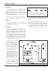
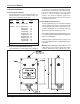
Instruction Manual 6.0 INSTALLATION 6.1 Gas Sensor Module Locations The gas sensor module is a diffusion type sensor that should be located close to the anticipated source or destination of the gas hazard. For heavy gases such as H2S install the module within 24 inches of the ground. For lighter gases such as CO and combustible gases use a higher elevation.
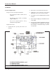
Instruction Manual Figure 6.
Instruction Manual 7.
Instruction Manual 8.