
Product Overview


Siemens Building Technologies CA1N4591E / 11.1998
Landis & Staefa Division 3/6
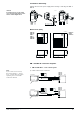
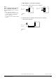
Installation / Mounting
Always disconnect the power supply before fitting or removing the ZM.. or
ZM../A.
9F681 A
9F676 A
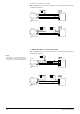
Dimensions [mm]
Caution:
It is important to use the cable
cross-sections appropriate to the
various cable lengths used.
9F677 A
B
ZM2.. max ø 13.1 mm
A
C
ZM1.. max ø 11.8 mm
max 4 mm
2
60 90
76
40
115
40
92.00552 C
ZM100/A
ZM101/A
ZM110
ZM111
ZM120/A
ZM121/A
ZM200/A
ZM210
ZM220/A
ZM.. and ZM../A connection diagrams
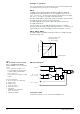
1 ZM../A with DC 0 ...10 V control signal
a) 3-wire connection to controller
Note
If, for reasons of cross-section,
the AC 24 V and DC 0 ...10 V (or
DC 4 ... 20 mA) cables are routed
separately, the AC 24 V cable
need not be twisted.
50211
1
2
3
4
~
~
–
+
~
+
AC 24 V
ZM100/A
ZM101/A
ZM200/A
⊥
DC 0 ... 10 V
AC 24 V
5
6
Controller
Twisted pairs
Controller
Twisted pairs
50627
1
2
3
4
~
~
–
+
~
+
AC 24 V
ZM100/A
ZM101/A
ZM200/A
⊥
DC 0 ... 10 V
AC 24 V
5
6
AC 24 V