
Product Overview


CA1N4591E / 11.1998 Siemens Building Technologies
2/6 Landis & Staefa Division
Principle of operation
The control properties of the magnetic valve are not affected by the type
of terminal housing or the type of control signal.
ZM../A
Terminal housings ZM100/A, ZM101/A, ZM120/A, ZM121/A, ZM200/A
and ZM220/A are signal transducers / power amplifiers. They convert a
DC 0 ...10 V or DC 4 ... 20 mA control signal and an AC 24 V power supply
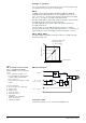
into a DC 0 ... 20 V phase cut signal (see diagram below).
The differential amplifier with signal inputs (3) and (4) is isolated from the
AC supply by a high resistance (see block diagram).
For 3-wire applications the signal negative (3) must be connected to
AC supply terminal (1).
It is also possible to use the ZM../A terminal housing as a "straight-
through" electrical housing, supplied directly with a DC 0 ... 20 V phase cut
signal. In this case, the AC 24 V supply voltage must NOT be connected.
ZM110, ZM111, ZM210
The ZM110, ZM111 and ZM210 terminal housings are "straight-through"
electrical housings only.
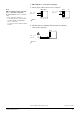
ZM../A block diagram
1
2
3
4
5
6
–
–
+
50203 B
~
AC 24 V
~
+
DC 0 ... 10 V
(DC 4 ... 20 mA)
DC 0 ... 20 V Phs
T
R
G
V
E
Q
M
–
+
0
10
15
[V]
5
12
7,5
16
10
20
0
4
[V]
[mA]
20
92.00551
Typical operating range
of magnetic valve
(0 ... 100 % stroke)
Control signal
Phase cut signal
Key to block diagram:
E Electronic phase cut conditioning
G Bridge rectifier
M Magnetic valve
Q Phase cut output
R 56 k
Ω
input resistors
T 150
Ω
shunt
(ZM120/A, 121/A, 220/A with
DC 4 ... 20 mA only)
V Differential amplifier
Transformer sizing
Transformer power P
Tra
= 1.4 · Sum of the individual loads
Note
ZM../A terminal housing used with
DC 0 … 20 V phase cut signals:
Do not connect AC 24 V to Terminals 1
and 2.
Connect Terminal 5, (marked " – ")
– to the appropriate Y output terminal
on UNICO, KLIMO and MULTIREG
(type 9 controllers)
– to Terminal 2 on type NKOA terminal
modules.