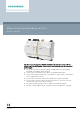
Meters and Energy Cost Allocation M-bus Level Converter/Repeater 250 WTX631-GA0090 The level converter/repeater WTX631-GA0090 is the interface between M-bus devices and a readout system. It consists of a level converter and the associated power supply. ● ● ● ● ● ● ● A6V11742346_en--_b 2020-08-24 The level converter and associated power supply form a unit: No addition transformer or auxiliary power required Connect up to 250 M-bus devices (max.
Use The level converter is a communication interface to readout up to 250 M-bus devices (simple M-bus loads). The data is read via a M-bus web server WTV676, a PXC device, or via other M-bus read/configuration systems. Multiple level converters can be connected in parallel on one M-bus network. When connected to a M-bus web server, up to six level converters can be connected in parallel. Up to six level converters/repeaters can be connected in series (max. five level converters as repeaters).
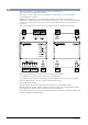
Functions Operating modes The power supply can be employed as follows: ● To power the level converter 1 ● Smart Infrastructure Level converter/repeater 2 Power supply To power the M-bus web server WTV676.. (DC 24 V). A Web server WTV676.. 1 Connection web server WTV676..
The level converter can be used in various ways: Reading data over the M-bus web server The level converter is connected as a slave to a M-bus web server WTV676.. to extend the M-bus network. Up to six level converters can be connected in parallel. A max. of six level converters (max. five repeaters) can be connected in series to overcome large distances. The data is read via the M-bus web server. A maximum of 250 M-bus devices can be read via M-bus web server.
Reading data over the RS-232 or RS-485 interface The level converter can be connected as master via the RS-232 or RS-485 interface to a PXC device or a PC to read device data. A Level converter (RS232 or RS485 interface) B PC or M-bus devices NOTICE The level converter WTX631-GA0090 does not have a mini USB interface to locally read the data. The device data cannot be read locally with the ACT531 software.
Level converter as standalone device with up to 250 connected M-bus devices The level converter can be used as the master on one M-bus network with up to 250 M-bus devices.
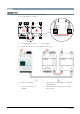
Indicators The level converter has six LEDs on the front side for indicating the operating state. Run TX M-Bus RX M-Bus Short Circuit Overload Power Run… The (green) LED indicates the operational state of the device. ● Blinking at 1 Hz (slow) -> Device functions are being set up. No communication. ● Blinking at 0 Hz (fast) -> Device update pending. ● On -> The device is operational. TX M-bus The (green) LED indicates the transmission state on the M-bus network (terminals 9 and 10).
Technical design Topology The M-bus permits various network topologies. The devices can be connected to the level converter in a line, bus, star, or tree topology, or a combination thereof. Ring topology is not permitted. Bus cable polarity is not relevant, simplifying installation.
Tree topology Combination of topologies Ring topology Smart Infrastructure 9 A6V11742346_en--_b 2020-08-24
M-bus Address M-bus uses two types of addresses to recognize devices: ● Primary addressing: Up to 250 primary addresses can be assigned to a M-bus system. The primary address is normally assigned during device commissioning. Pure primary addressing is not possible if more than 250 devices are read on the M-bus network. ● Secondary addressing: Secondary addressing consists of 8 bytes and permits the assignment of any number.
Connection terminals The device as the following connection terminals / LEDs. A Mains voltage AC 230 V B Output for web server WTV676 power supply (DC 24 V) C Connect the power supply (Vout LC) to the level converter (Vin LC) (do not use for other purposes) D Serial interface RS232 and RS485 to connect to a PC or M-bus master RS-232 A = TX B = RX C = GND E Smart Infrastructure F Connections to the M-bus web server WTV676.. or master level converter if the level converter is used as repeater.
Type summary Order information Description Order number Type Level converter to power a max. 250 simple M-bus loads S55563-F159 WTX631-GA0090 Product inserts Mounting instructions for the level converter are included in the following languages: Bulgarian, German, English, Finnish, French, Greek, Italian, Croatian, Lithuanian, Dutch, Norwegian, Polish, Slovakian, Slovenian, Spanish, Czech, Turkish, and Hungarian.
Notes Safety CAUTION National safety regulations Failure to comply with national safety regulations may result in personal injury and property damage. ● Observe national provisions and comply with the appropriate safety regulations. Disposal The device is considered an electronic device for disposal in accordance with the European Guidelines and may not be disposed of as domestic garbage. ● Dispose of the device through channels provided for this purpose.
Technical data Power supply Operating voltage AC 110…240 V AC frequency 47…63 Hz Power consumption 6 W + 0.07 W for each connected M-bus device Maximum power consumption 45 W, 45 VA Vout: DC 24 V, max. 15 VA Power consumption level converter (in series) ≤3 mA (2 M-bus loads) Internal fuse PTC resistance and varistor Fusing of supply lines Circuit breaker Max.
M-bus master network Max. number of level converters in parallel per network Up to 6 slave level converters Max. number of serial level converters per network 6 level converters, of which 5 repeaters Bus power Minimum 30 V Bus current Maximum 90 mA Protection against short circuits Yes Galvanic isolation Interface RS-232. Connection to a PC and connection to an M-bus web server WTV676..
Dimensions Length x Width x Height 110 x 71 x 62 mm per device (including terminals) Weight Level converter with mounting instructions 0.392 kg for both devices Packaging 0.055 kg Mounting Mounting type On 35mm DIN rails (EN60715) Dimensions Issued by Siemens Switzerland Ltd Smart Infrastructure Global Headquarters Theilerstrasse 1a CH-6300 Zug Tel. +41 58 724 2424 www.siemens.