
Basic Documentation

34 / 130
Siemens M-bus level converter and M-bus web server A6V11157985_en--_f
Smart Infrastructure Level converter commissioning 2021-06-21
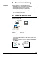
6 Level converter commissioning
Ensure the following prior to commissioning the level converter:
The electrical connection must be fused (non-renewable fuse or circuit breaker)
The power supply must be at the device's rated voltage.
The power supply must be sufficient to operate the device.
Commissioning commences once power is connected to the level converter.
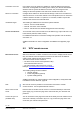
Additional settings are also available if using the ACT531 software.
Operation and any errors are indicated with LEDs on the front side.
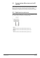
6.1 Display elements
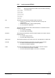
6.1.1 Level converter WTV531..
The level converter has six LEDs on the front side for indicating
the operating state.
The LED indicates the USB interface connection state.
Flashes 2 x The device is ready to connect to a PC using a mini USB-B
cable.
Flashes 5 x The device is connected to and correctly recognized by the PC.
The LED indicates the transmission state on the M-bus master
(terminals 6 and 7).
On Data transmitting.
Off No data transmission.
The LED indicates the receive state on the M-bus master (terminals 6 and 7).
On Data is being received.
Off No data is being received.
The LED indicates the state of the M-bus power supply.
On Bus overload (short circuit or too many devices on the bus).
Off No faults recognized.
The LED indicates that bus power is correct and there are no anomalies.
On M-bus power is sufficient for trouble-free operation.
Off M-bus power is insufficient for trouble-free operation.
The LED indicates the state of the level converter power supply.
On The device power supply is correct.
Off Device power is not correct or unavailable.
Prerequisites
Note level converter
WTV531..
USB Activity
TXD
RXD
M-bus Error
M-bus Ready
Power