
Basic Documentation

25 / 130
Siemens M-bus level converter and M-bus web server A6V11157985_en--_f
Smart Infrastructure 2021-06-21
4.4.3 RF converter
Select a power supply AC 100...240 V as described in the technical data.
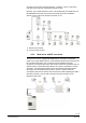
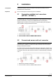
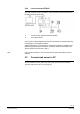
4.4.3.1 Locating RF converters
The RF converter receives data from one or more wireless devices within a radio
system per EN13757-4. The RF converter forwards the received data to the web
server.
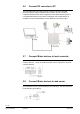
You can power the RF converter over a USB connection using an external battery
(>= 5000mAh; @5V; >= 1.5A) to help in the search for the optimum location. The
RF converter remains mobile during the scan and can be moved to the location
with the best signal reception.
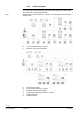
A flashing blue LED indicates that the location is unfavorable and there is no
connection to the web server.
Once a favorable location has been found and a connection set up from the device
to the web server via the RF converter, the blue LED stops flashing and the search
for wireless devices begins.
The green LEDs only light up once a connection to the web server has been
established. The number of green LEDs that are illuminated indicates the signal
strength. When all four LEDs light up, you have a strong signal. The blue LED
remains permanently illuminated.
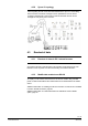
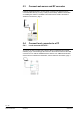
The minimum distance between RF converters is 5 m. The RF converter must be
at least 20 cm from the ceiling and the wall where it is mounted.
4.5 M-bus
4.5.1 M-bus addressing
M-bus uses two addressing types to recognize and communicate with wired M-bus
devices:
Primary addressing:
Up to 250 primary addresses can be assigned per line to an M-bus system. The
primary address is normally assigned during M-bus device commissioning.
Secondary addressing:
Secondary addressing consists of 8 digits and permits the assignment of any
number. In the default setting, the secondary address for a M-bus device
matches the serial number issued by the device manufacturer. The assignment
prevents address conflicts on the M-bus and permits addressing of more than
500 M-bus devices on a system.
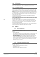
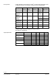
4.5.2 Sizing the wired M-bus system
Allowable cable types:
Shielded telephone cable 0.5 mm
2
(4 x 0.8 mm)
NYM cable (1.5 mm
2
)
Maximum capacitive cable load of 152 nF/km
Note