
Basic Documentation

15 / 130
Siemens M-bus level converter and M-bus web server A6V11157985_en--_f
Smart Infrastructure 2021-06-21
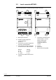
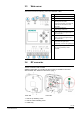
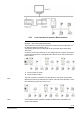
3.3 Web server
The web server has the following connection terminals / LEDs.
A Ethernet connection
B USB connection (no function)
C Antenna connection
D Terminals A, B, C: Connections for
following level converters.
Terminals M1 and M2: Connections for
M-bus devices and follow-on level
converters
E Terminals (16) and (17):
Power supply AC/DC 24 V
F Terminals (12) and (13):
Relay connections for digital output 1,
max. AC/DC 30 V
G Terminals (14) and (15):
Relay connections for digital output 2,
max. AC/DC 30 V
H Terminals (9), (10) and (11):
Connections for digital inputs.
Terminal (8): reference for digital inputs.
I Terminals (6) and (7) are not used.
Do not apply electricity to these
terminals.
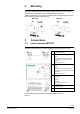
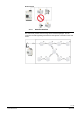
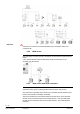
3.4 RF converter
The RF converter is wall mounted.
Additional information on mounting the RF converter is available in document
A6V11135905. See "Reference documents", page 7.
Rear side Front side
1. Hole for top attaching screw
2. Hole for bottom attaching screw
3. Cable entry