s M-bus web server WTV676-HB6035 M-bus level converter WTV531-GA5060 M-bus level converter WTX631-GA0090 RF converter WTX660-E05060 User’s guide A6V11157985_en--_f 2021-06-21 Smart Infrastructure
Legal notice Technical specifications and availability subject to change without notice. Transmittal, reproduction, dissemination and/or editing of this document as well as utilization of its contents and communication thereof to others without express authorization are prohibited. Offenders will be held liable for payment of damages. All rights created by patent grant or registration of a utility model or design patent are reserved. Issued by: Siemens Switzerland Ltd.
Contents Cyber security disclaimer ...................................................................................6 0 About this document ...........................................................................7 0.1 Revision history .....................................................................................7 0.2 Reference documents ............................................................................7 0.3 0.3.1 0.3.2 0.3.3 0.3.4 Before you start ...............................
.5 4.5.1 4.5.2 M-bus .................................................................................................. 25 M-bus addressing ................................................................................ 25 Sizing the wired M-bus system............................................................. 25 5 Installation ......................................................................................... 27 5.1 Connecting multiple level converters (WTV531.., WTX631..) ................
11.1 Select default operating language ........................................................ 48 11.2 Buttons ................................................................................................48 11.3 Operating.............................................................................................49 12 Web server browser operation .......................................................... 61 12.1 Registration & login ..............................................................
Cyber security disclaimer Siemens products and solutions include security functions to ensure the secure operation of building automation and control, fire safety, security management, and physical security systems. The security functions on these products and solutions are important components of a comprehensive security concept.
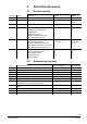
0 About this document 0.1 Revision history Version Date Changes Section Pages 1.0 30-Jun-2017 First edition 2.0 31-May-2018 Integration Synco IC 1, 4, 5, 8, 11, 12 12-Oct-2018 Added trend functions 1.3, 4, 5, 8, 12 4.0 28-Feb-2019 3, 4, 5, 11, 12 5.0 22.10.2019 6.0 21.06.
0.3 Before you start 0.3.1 Copyright This document may be duplicated and distributed only with the express permission of Siemens and may be passed on only to authorized persons or companies with the required technical knowledge. 0.3.2 Quality assurance These documents were prepared with great care. The contents of all documents are checked at regular intervals. All necessary corrections are included in subsequent versions.
1 Overview 1.1 Device functions 1.1.1 Level converter WTV531.. The level converter WTV531-GA5060 is a communications interface for reading up to 60 M-bus devices (simple M-bus loads). The data is read out: Locally using the ACT531 PC software via USB Locally using the ACT531 PC software via the RS-232 interface Via the M-bus web server WTV534.., WTV676.. Via Desigo CC Up to six level converters can be connected in parallel to a M-bus web server WTV676.. (Master) on a M-bus network.
1.1.3 Web server WTV676.. The web server reads M-bus devices connected directly to the web server as well as M-bus devices connected to the web server via level converters and wireless devices connected to the web server via an RF converter. It can be used: Alone with up to 20 directly connected, wired M-bus devices As a master on an M-bus network with up to six connected level converters and a total of 60 logical M-bus devices per line. Up to 250 M-bus devices (max. 250 M-bus meters, max.
1.2 M-bus properties 1.2.1 Wired M-bus The M-bus system (Meter Bus) is a communications protocol per EN13757-2.
1.3 Synco IC Synco IC integrates the M-bus web server WTV676-HB6035 easily and securely to the cloud. This permits the upload of billing data and alarm messages, Trend data to the cloud per customized settings and sends the information to the corresponding customers via email. The meter information can be saved on the cloud together with additional plant data. Multiple web servers can also be managed on a joint Synco IC account. 1.3.
2 Mounting The level converter and web server are designed for mounting on 35 mm rails. They take up the equivalent of four standard modules on the rails. Additional information on mounting is available in the mounting instructions for the level converter [3] and the web server [5]. Mounting Removal 3 Connections 3.1 Level converter WTV531.. The level converter WTV531.. has the following connection terminals / LEDs.
3.2 Level converter WTX631.. Level converter WTX631.. has the following connection terminals: F D I (1) (2) (5) (3) (4) (3) (4) (5) D E F A B C (1) (2) (4) (5) Power 230Vac RS-232 RS-485 G A WTX631-GA090 POWER SUPPLY WTX631-GA0090 LEVEL CONVERTER Run TX M-Bus H RX M-Bus Short Circuit Overload Power M-Bus MASTER (6) (6) (6) (6) (7) E (7) (7) (7) Vin LC Vout LC VA VB VA VB (8) (9) C A Mains power AC 230 V B Output for power supply level converter WTX631..
3.3 Web server The web server has the following connection terminals / LEDs. A Ethernet connection B USB connection (no function) C Antenna connection D Terminals A, B, C: Connections for following level converters. Terminals M1 and M2: Connections for M-bus devices and follow-on level converters E Terminals (16) and (17): Power supply AC/DC 24 V F Terminals (12) and (13): Relay connections for digital output 1, max.
4 Engineering 4.1 Topology 4.1.1 Wired M-bus devices The M-bus permits various network topologies. The devices can be connected to the level converter or the web server in a line, bus, star, or tree topology, or a combination thereof. Ring topology is not permitted. Bus cable polarity is not relevant, simplifying installation.
Ring topology 4.1.2 Wireless devices The web server permits read out using various network topologies. The RF converters are self-organizing and search for the optimum connection to the web server.
4.2 Operation modes 4.2.1 Level converter WTV531.. with ACT531 software The level converter is used as the communication interface between M-bus devices and a laptop using the ACT531 software. The ACT531 software can read up to max. of 1,000 devices. Up to 60 devices (60 unit M-bus loads) can be connected. The data is read locally using a USB connection or via the RS-232 interface. A Level converter as master B Laptop with ACT531 software A Level converter as master B Laptop with ACT531 software 4.2.
4.2.3 Level converter to extend a M-bus network The level converter is used to extend the M-bus system by 60 (WTV531..) or 250 (WTX631..) (60 or 250 simple M-bus loads). The master level converter (A) is connected to a M-bus web server WTV676.. via the RS-232 interface (terminals A, B, C). The following slave level converters (B) can be connected via the M-bus slave connection. A maximum of six level converters can be combined to form a network.
Important PC must be connected to the master level converter WTV531.. (A) to readout data and other PCs cannot be connected simultaneously connected to slave level converters (B). 4.2.4 Web server The web server is used to read up to 20 directly connected devices (20 unit M-bus loads). A PC / Internet browser reads the data either locally over Ethernet or from anywhere over the Internet. 4.2.
A maximum of six level converters (WTV531.., WTX631..) can be connected to each line with a maximum of 250 M-bus devices per line. Moreover, up to 20 M-bus devices can be connected directly to terminals M1 and M2. Additional information on the M-bus web server terminals is available in section 'Connect web server and level converter, pg. 27. A Web server as master B Level converter as slave 4.2.
4.2.7 Note Combined plants One web server can simultaneously read out up to 500 wired M-bus devices (250 per line) and up to 2,500 wireless devices. Different level converters (WTV531.., WTX631..) are permitted on the same plant and same line. A B C Web server as master Level converter WTV531.. as slave M-bus-RF converter as participant A B C D 1 2 Web server as master Level converter WTX631.. as slave M-bus-RF converter as participant Level converter (repeater) WTX631..
4.2.8 Synco IC topology After integrating the web server WTV676-HB6035 in the Synco IC cloud, billing data, trend data, and alarm messages can be uploaded and sent to various recipients. Multiple M-bus web servers as well as OZW web servers can be managed on one joint Synco IC account. 4.3 Readout of data 4.3.
4.4 Power supply 4.4.1 Level converter WTV531.., WTX631.. Please note when designing the power supply for the level converter, that M-bus devices require additional current of up to 20 mA when communicating. For M-bus address conflicts during commissioning, multiple M-bus devices can draw power at the same time and it adds up. The level converter limits power on the M-bus to a maximum of 200 mA.
4.4.3 RF converter Select a power supply AC 100...240 V as described in the technical data. 4.4.3.1 Note Locating RF converters The RF converter receives data from one or more wireless devices within a radio system per EN13757-4. The RF converter forwards the received data to the web server. You can power the RF converter over a USB connection using an external battery (>= 5000mAh; @5V; >= 1.5A) to help in the search for the optimum location.
Bus expansion If using cable with a cross-section of 0.6 mm2, you must cut the information in half on "Maximum distance" and "Number of devices" from the following table. Plant type Maximum Total cable distance length Cable diameter Small residential buildings Large residential buildings Small developments Large developments Direct vicinity Point-to-point connection 350 m 1000 m 0.8 mm2 350 m 4000 m 0.
5 Installation Prerequisite Connections between devices are based on the selected operating mode as illustrated in the sections below. Important Do not connect power to the devices prior to installation! 5.1 Connecting multiple level converters (WTV531.., WTX631..) To extend the M-bus, connect terminals (6) and (7) on the existing level converter (master) to terminals (1) and (2) on the additional level converter (slave).
5.3 Connect web server and RF converter Install the supplied antenna to access the RF converter. The antenna can be connected either directly or using a cable (recommended). Additional information on installing the antenna is available in document A6V11157964. See Section "Reference documents", page 7. 5.4 Connect level converter to a PC 5.4.1 Level converter WTV531..
5.4.2 Level converter WTX631.. The level converter can be connected to a PC as master via interface RS-232 or RS-485 to read out device data. A Level converter (interface RS232 or RS485) B PC or M-bus device The TX Open module integrates M-bus devices via RS-232 or RS-485 interface to in the Desigo CC management platform. Addtional information on the Desigo CC management platform is available in the Engineering guide 'Desigo TM TX Open, TX M-bus', document CM110572.
5.6 Connect RF converter to PC The mini USB type B connection on the RF converter connects to the USB interface on the PC with the installed ACT531 software. The RF converter is configured with the ACT531 M-bus configuration and readout software, version ≥ 2.0. Additional information on the M-bus configuration and readout software is available in document A6V10844345, section Reference documents, page 7. 5.
5.9 Connect wireless M-bus devices to the RF converter All RF converters must be part of the same radio network (mesh network). Do not place the devices too far from one another on the same floor and avoid any larger barriers such as cement walls or metal construction. The distance between individual devices on different floors cannot exceed more than just a few devices. 5.10 Digital inputs on web server Web server provides 3 digital inputs I1, I2, and I3 to connect potential-free contacts (e.g.
5.11 Digital outputs on web server The web server has two relays that can be used as digital outputs. They can connect a load or be used as contacts to activate other systems. Terminals O1 (13) and O2 (15) can be controlled locally on the web server or remotely via the Internet. Connect as follows to control, for example, a load: The load at the relay contacts may not exceed the following values: 5 A @ AC/DC 30 V (resistive load) 2 A @ AC/DC 30 V (inductive load cosφ = 0.4) 5.
Local display: You can enable or disable automatic report transmission to the cloud in the "Settings" menu. See Section "Operating", pg. 49. 5.12.2 Enable web server in Synco IC Change to the Synco IC portal to register the web server. The Synco IC portal is located at: https://www.siemens-syncoic.com/. Enter your email address and web server activation key on the Synco IC portal to register. You can view the activation key either on the web server browser or locally on the display.
6 Prerequisites Ensure the following prior to commissioning the level converter: Note level converter WTV531.. Level converter commissioning The electrical connection must be fused (non-renewable fuse or circuit breaker) The power supply must be at the device's rated voltage. The power supply must be sufficient to operate the device. Commissioning commences once power is connected to the level converter. Additional settings are also available if using the ACT531 software.
6.1.2 Level converter WTX631.. The level converter has six LEDs on the front side for indicating the operating state. Run The (green) LED indicates the operational state of the device. Flashes at 1 Hz (slowly) The device functions are set up. No communication. Flashes at 10 Hz (fast) Device update pending. On The device is operational. TX M-bus The (green) LED indicates the state of data transmission on the M-bus network (terminals 9 and 10). On Data is transmitting.
6.2 Troubleshooting the level converter The device does not switch on. The Power LED is off. Using a multimeter, check whether the required operating voltage of 24 V AC or DC is available at terminals (8) and (9). The M-bus Error LED is on Check M-bus wiring. There is a bus overload due to a short circuit between the bus cables or too many M-bus devices are connected. The M-Bus Ready LED is switched off.
7 Commission RF converters Determine the best location for the RF converter. The RF converter can be powered by an external battery (using its USB connection) to search for the optimum location. Additional information is available in Section "Locating RF converters", page 25. Ensure that all RF converters belong to the same radio network. Ensure that all RF converters have the same Mesh ID and same channel ID within a radio network.
Does not recognize all meters. Ensure that the unrecognized devices are not located too far from the RF converter and that the radio signal is not too weakened by cement or metal walls. Ensure that the unrecognized devices are loaded to the web server list and that contact to the wireless M-bus devices, recognized by the web server, is not interrupted. Please note that some wireless M-bus devices only transmit their data at intervals of multiple hours.
8 Prerequisites Web server commissioning Ensure the following prior to commissioning the web server: The electrical connection must be fused (fuse or circuit breaker) The power supply must be at the device's rated voltage. The power supply must be sufficient to operate the device. The router (if available) must be configured as per the description.
Connection over LAN Use a DHCP server for dynamic IP address or a fixed IP address if the PC and web server are integrated on an existing LAN. Contact your network administrator about the fixed or dynamic IP address to be used. You can change the LAN settings via the local operation of the web server. Details see section 10. Direct PC connection Configure the IP address on the PC network settings or web server so that the PC and web server are on the same network.
8.3 M-bus commissioning on web server After installation and after all connections are established, the M-bus is commissioned as per the following steps: Check M-bus On the level converter, check that the M-bus Ready LED is on and the M-Bus Error LED is off. First time log in You must set the web server language the first time web server is activated.
Continue settings on web server At the conclusion of the meter search, we recommend accessing the web server via the Internet browser to conclude the configuration. You can enter plant data and other settings via the Internet browser. For access to web server, see section “Connect web server to PC or LAN“, page 39. Enter meter name Assign each device a unique name, e.g. "Apartment 1, "Warehouse", "Hot water" to simplify evaluation of reports with consumption data or device information.
8.4 Enter device names to the wireless devices Commission RF converters on web server Assign each device a clear and unique name to each meter, for example, "Apartment 1", "Basement", "Hot water" to simplify the evaluation of reports on consumption data or device information on the web server. See Section Settings / Wireless devices / Device settings. Page 100. 8.5 Web server troubleshooting The device does not switch on. The green LED is off.
8.6 Web server integration in Synco IC The web server is registered in the cloud after entering the activation key for the Mbus web server WTV676 in the Synco IC portal. This billing data, trend data, and alarm messages (reports) is transmitted to Synco IC per customized settings as well as the distribution of information to the corresponding customers via email. You must select "Enable Synco IC reports" check box on the web server.
9 Level converter operation 9.1 Level converter WTV531.. The level converter WTV531.. has no operating elements. Any desired changes can be made using the ACT531 software. 9.2 Level converter WTX631.. The level converter WTX631.. has no operating elements. It can be connected via RS-232- or RS-485 interface and connected to a PC.
10 RF converter operation The RF converter consists of three housing components. The base, mounted on the wall (1); the removable cover (2), and the cable entry (3). The RF converter operating elements for the network are located in the lower part in the cable entry (3). The removable cover has the following LEDs. 1 Green LED 1 2 Green LED 2 3 Green LED 3 4 Green LED 4 5 Blue LED The cover for the cable entry has the following connections and buttons. 1 Power (AC 100..
10.1 Change mesh ID Change the mesh ID if the blue LED on the RF converter is permanently illuminated after installation and the web server is not switched on. Proceed as follows: Press buttons 2 and 3 at the same time for a few seconds. As soon you let go of the buttons, one or all the green LEDs start flashing. Note For a mesh ID ≥ 5, all the green LEDs flash simultaneously. Otherwise, only the corresponding green LED flashes. For example, LED 1 flashes for a Mesh ID = 1.
11 Web server operation on the device 11.1 Select default operating language The language set on the display is the default language. You can set the default operating language directly on the display. After entering the password, you can select the language on the main menu at Settings / System / Select language by pressing the and buttons.
11.3 Operating Measured data and basic settings are displayed on a color display. The display switches off automatically to save energy after 10 minutes. Access code entry Press a navigation button to switch on the display. The display to enter the access code opens. Enter the access code. The cursor flashes at the current position. Select individual numbers using the arrow keys and and confirm with the OK button. The cursor goes to the next position on the 8-digit access code.
Reset access code Important Reset user account In the event you are unable to access the local display using the access code, you can reset the access code via web browse as long as you know your login data for the web browser. Additional information on resetting the local access code via web browser is available in section 'Settings', 'System', pg. 79. For security reasons, define a new access code locally on the web server as soon as possible after a reset.
Main menu The main menu displays after correctly entering the access code. It consists of five pages: System info, Wire meters, Wired search, Search RF and Settings. System info Includes information on web server and connection status and to the activation key. Wired meters Displays the list of connected M-bus devices and makes it possible to display the data. Wired search Starts the search for connected device as per the last saved changes.
System info menu Select the System info main menu and press the OK button to go to the submenu. Plant name Serial number (required for support calls). LCD UI Version (local UI version) M-bus firmware version LAN connection status and IP address (if connection is available). Internet connection status and public IP address for external access (if connection is available).
Activation key for Synco IC Synco IC status WLAN status (displays the remaining time for the WLAN connection) WLAN address (displays the WLAN address, if active) Wired meters menu WLAN status (Disable connection) Select the Wired meters main menu and press OK to go to the sub menus 53 / 130 Siemens Smart Infrastructure M-bus level converter and M-bus web server A6V11157985_en--_f 2021-06-21
List of saved meters. Each meter is identified by the first 8 digits of the serial number (e.g. 05434563). The following symbols are displayed in the first column: OK: The last readout was successful. Device error: An error was reported to the web server via M-bus. Communications error: No communications with the device. You can navigate through the list with the and navigation buttons. Press OK to go to the data for the selected meter.
Readout time Displays the time of the meter readout. M-bus description Displays the field description as per the M-bus protocol. M-bus storage: Displays the storage number of the displayed M-bus data point. See the meter documentation for additional information. M-bus tariff Displays the tariff number of the displayed M-bus data point. See the meter documentation for additional information. M-bus subunit Displays the number of the subunit for the M-bus data point.
Scan type Select the M-bus addressing type used in the scan: Primary + secondary address / Primary address / Secondary address Check meters and save A list of devices found is displayed after the meter scan is finished. Press OK to save all newly found meters and add them to the device list. The ESC button does not add the newly found meters to the device list. To edit meter settings over web operation, see menu Settings / Wired devices / Device settings (see page 89 et seq.).
Settings menu The Settings menu has three sub-menus: – – – System LAN RF network Synco IC You can navigate between the submenus with the and navigation buttons. You can navigate within the submenus with the and navigation buttons. The OK button selects a field for editing and then confirms the entered value.
System System date The System sub-menu has the following settings: Enter the current date of the web server. System time Enter the current time of the web server. Select language Select the language on the web server display. Important The language set locally on the web server is also used for sending emails and to generate reports and alarm notifications. As a result, it is important to select the correct language during web server commissioning.
Primary DNS The DNS name server (domain name system) on the Internet connects a globally valid name to a domain with an IP address (e.g. domain www.siemens.com with IP address 146.254.191.150). The setting corresponds to the IP address for the next router or DNS name server that recognizes for its part a queried name (domain) or another DNS name server. The setting is typically identical to the setting for the standard Gateway.
Note The WLAN connection remains active for up to 12 hours after enabling. Press the OK button and enter the web server access code to display additional information on the WLAN connection or to disable the WLAN connection on the web server on the display. Additional information on the web server access code is available in section 'Access code entry', page 49.
12 Web server browser operation 12.1 Registration & login Prerequisite The web server and the PC are connected to the same network and the network access is configured. See section "Connect web server to PC or LAN", page 39. Initial registration To access web server, enter the web server IP address (e.g. https://192.168.1.110) in the browser (Chrome, Safari, Firefox). Complete the mandatory fields: Email Username Password Confirm password to register and receive access to the web server.
The password must meet the following conditions: At least 8 characters Three of the following 4 criteria must be fulfilled: – Lowercase letters – Uppercase letters – A digit – A special character Important The Register button is only enabled after meeting the password conditions. Sign in You are notified if you enter an incorrect login or password. The login is locked on the web server for five minutes (300 s) after a maximum of six attempts.
'Mobile' option Note The 'Mobile' option reads the web server on site using your mobile phone or tablet over WLAN. Make sure the WLAN connection is active on the web server. Additional information on enabling WLAN and displaying the IP address is available in section 'WLAN connection, page 59. To connect the mobile device to the web server, open the browser on your mobile device and enter the IP address of the web server (e.g. https://192.168.0.10).
12.2 Home 1 The following information is displayed on the title line: Name of the logged in user. Language selection. Information on "Open source software" packets and licenses. 2 Primary navigation using the main menus: Plant status (as of page 65) Settings (as of page 79) Export data (as of page 107) User account (as of page 121) 3 Status Information: M-bus status Status M-bus radio Number of logged on users Date and time.
12.2.1 Select the web server language (software interface) You can set the operating language for the software interface in the title line to the right. The following languages are available: English German Italian French Dutch Important The login always used the default language that was selected and is displayed on the display. The language setting in the login window applies exclusively to the current session.
WLAN status WLAN: You can enable or disable the WLAN connection using the 'Enable' or 'Disable' button. Synco IC reporting: Display the current status of automatic transmission of Synco IC reports to the cloud. See Section "Setup automatic reports, as pg. 109. Plant name: Name of the plant. Web server serial number Model: Displays the web server type designation. Address: Plant location. System clock: Current web server date and time.
Event log The event log records the following events: Alarms and warnings Change of state of inputs/outputs Send status of emails Send status of information via FTP The following information can be read by event: Event status Start date/time End date/time Category Reference Description The following event status can be displayed: Device OK: Reported alarms or warnings are corrected. Device fault: A device fault reported via M-bus.
Individual lines on the event log or the entire list can be deleted. Proceed as follows: Note Delete individual rows: Select the event check box to be deleted and then click Delete event in the upper end of the list. The Delete event is enabled if at least one line is selected. Delete complete list: Select the check box on the title line and then Delete event to irretrievably delete the entire event log. Display only active events to list only currently pending alarms and input/output status.
Web access The web access connects to the web server from anywhere. The web access is enabled by default and can be disabled with the 'Disable' button. Note If deactivated, the web access can only be activated locally. The web server link opens the web server login page. You must login with user name and password to proceed to the web server home page. 12.3.2 Wired devices Wired devices The Wire devices overview lists all M-bus devices located on the network in an abbreviated form.
Click a line to list additional device information. The information that cannot be changed are grouped into three categories: Device information: General device data (name, description, ID, medium, etc.) Last readout timestamp: Displays the values of the last 6 readouts. Alarm status: Displays the faults pending on the device and which ones are registered and sent via email.
The following information can be read per line (i.e. per M-bus wireless devices): • Medium • Serial number • Availability of device with optional image • Device name • Description • Main value (=> selectable, see Section “Wireless devices, as page 100) • Date/time of last device reading • Device status The following device status can be displayed: Device is OK Device fault Communication error Click a line to list additional information on a particular device.
12.3.4 Controller Controller The controller overview lists all RVD controllers (compact) connected to the network.
This information cannot be edited and compiled into the following categories: • Communication state: Indicates whether the device can be reached on the network • Time stamp for last readout: Displays the data and time of the last readout • Alarm state: Lists the current alarm messages with date and time • Data point: Displays the plant-specific diagram and the associated data points. Additional information is available in section 'Data point settings'.
Configuration In the 'Configuration' pane, various setting parameters for RVD controllers can be displayed, edited, backed up and restored. The data from the last readout of the controller is displayed (see last readout timestamp). Click 'Readout now' to start manual readout. The 'Configuration' pane is divided into: - Back and restore controller settings - Plant-specific setting parameters (e.g. for heating circuits or DHW, etc.) - Schedulers for operation (e.g. heating circuit or DHW, etc.
Note Restore backup file Note To reset the entered file name, click . This displays the suggested file name. To delete a backup file from the web server, click . You can select the backup file and upload it if you want to return to prior controller settings. Access the backup file as follows: - On the web server: Select the backup file from the list. - On the desktop: Click 'Import' and select the backup file.
Legionella function frequency Time Scheduler heating circuit 1 Monday Scheduler heating circuit 1 Tuesday Scheduler heating circuit 1 Wednesday Scheduler heating circuit 1 Thursday Scheduler heating circuit 1 Friday Scheduler heating circuit 1 Saturday Scheduler heating circuit 1 Sunday Scheduler HC2 Monday Scheduler HC2 Tuesday Scheduler HC2 Wednesday Scheduler HC2 Thursday Scheduler HC2 Friday Scheduler HC2 Saturday Scheduler HC2 Sunday Scheduler HW Monday Scheduler HW Tuesday Scheduler HW Wednesday Sched
Note Parameters outside the value range are highlighted in red. No data is written to the controller in the event of erroneous values. Scheduler The scheduler defines when a part of the plant, e.g. a heating circuit or DHW plant, is operated. For example, you can program a time switch for individual days of the week (Monday through Sunday) in the pane 'Scheduler for heating circuit 1'. Enter the start time and end time of operation. Multiple entries per day are possible.
12.3.5 Inputs/outputs Inputs/outputs Displays the current status (open/closed) of inputs/outputs on web server. . The following information can be read by input/output: Image of connection terminals on web server Short description: I = Input, O = Output Status: Open/closed Designation Click Switch to manually switch the digital outputs.
12.4 Settings 12.4.1 System Plant data The following plant data can be assigned to web server: Note Plant name Address Installer name Customer name Install date (the current date by default) The edited data must be confirmed with Save. The plant name and address are displayed on the home page in the lower section to easily ID the web server, even before logging in.
Alarms As soon as web server detects an alarm, it sends an alarm notification to the designated email address(es): Emails are only sent if Enable alarm notifications via email is selected. The alarm notification can be simultaneously sent to multiple recipients. Multiple email addresses must be separated by a semi-colon (;). The email subject line can be individually set to simplify classification in the event of multiple plants.
System settings System settings has four areas: 1 System clock: You can automatically sync the system clock with the PC or enter it manually. 2 Report settings: You can select whether to use a period or a comma as the decimal separator. 3 System restart: You can remotely restart the web server with System restart. 4 Reset access code local display You can reset the access code for local access on web server.
You are notified that your system is up-to-date if no newer firmware version is found. You are notified that an update is available for your system if a newer firmware version is found. Load firmware To load the available firmware on the web server, click 'Download'. As soon as the firmware is loaded to the web server, the button 'Update' is displayed. Install firmware To install the firmware on the web server, click the 'Update' button. The update may take a few minutes.
After restart, the log-in page for the web server displayed. Log on again on the web server. Additional information on log in is available in the section 'Sign in Note You can close and reopen the web browser if the update takes more than 15 minutes. Check the update under 'Settings' > 'System' > 'Maintenance', to ensure the installed version on the server matches the available version. See section 'Update firmware online'. Firmware as of version is available online as of SIE.WTV676_WI-2.47_FW-3.7-182.6.
Important After a firmware update all data are available again. It is recommended to do a backup and to save the data on a PC before the actualization. Backup/restore All web server data is backed up and restored on this page. Important We recommend regularly backing up web server data.
12.4.2 Network Network settings The following information and settings are available (for additional details, see Section “M-bus commissioning on web server”, page 41): Web server MAC address. External port for web server: This setting is only used to add the external port to the external IP address which is part of the email header. The external port number must be the same as the external port number used in the port forwarding settings of the router, see page 123.
WTV remote access Web server WTV676.. and the router must be on the same network to use remote access. Check the IP address of the web server and the gateway (router) in menu 'Settings' > 'Network' > 'Network settings'. Note Ask the network administrator when operating the web server on a customer’s network. Check the status of the Internet connection in menu 'Plant status' > 'System status' > 'System information'. The same menu also displays if a connection is active to Synco IC.
Email configuration The following data must be saved on web server to send emails: Email server settings The following email server settings are available: Important SMTP server name: The address for the SMTP server. SMTP port: The port number used by the SMTP server. SMTP security: Selection of either SSL or TLS security. The setting NO sends the emails without encryption; do not use this setting for security reasons.
Dynamic DNS The web server can communicate directly with the fixed IP address or domain if a fixed IP address or domain (e.g. www.myname.com) is available for the Internet connection. Dynamic DNS settings DNS servers are available on the Internet for dynamic IP addresses that connect customized domain names with dynamic IP-Addresses of the web server. Registration You must first set up an account at the provider to use the DynDNS server.
Server connection test You can test the connection to the DynDNS server. The results are displayed. 12.4.3 Wired devices Device settings In this panel, you have access to the device list and can change settings. Note The list is empty if no device search has been run. The devices that are found and saved are displayed on the list after a device search.
Device list First column: Displays the medium M-bus line: Displays the M-bus line to which the device is connected. Lines M1M2 and ABC are available. Serial number: Displays the meter serial number Device name: Displays the meter name as entered under device name Description: Displays the text entered under Description 1 : Indicates that a product image is available for the device. Manufacturer code: Displays the 3-letter code of the device manufacturer.
Device settings Click the device line to view the settings for the device: Free text settings: Device name: You can assign a name to the device (e.g. Apartment 123). Description 1: Device description as indicated in the device list. Description 2: Additional description Scan interval: 15 min. / 60 min., 6 h, 12 h, 1 day, 7 days, 1 month Installation date. The device image can be set by clicking the as needed. You can select the appropriate image from the web server device database.
User description: The data point designation can be edited. M-bus description: Data point designation as per the M-bus specification Standard report – Data point mapping: Assigns data points to predefined columns on the standard report. Only one data point can be assigned to a specific column for each device. Data points with the "none" setting are not displayed in the standard report. Custom Report – Data point to be included: Select the data points to be included in the custom report.
The following information and settings are available. LOG: Displays whether the error message was registered in the event log. Email: Displays whether an email was sent due to the error message. Event name: The event name is predefined. It can, however, be changed as needed. Event type: Displays the event type received from the device. Status: Displays whether the alarm is active or not active.
The display is structed as follows: Search field List of all controllers (device list) found on M-bus Settings that can be edited (Device details) Data point settings Search field Enter the serial number, device name, or device description in the search field to filter by devices. Press enter to display the search results. Delete the content of the search field to remove the filter and press enter.
It is easier to edit the device information in xls or csv formats, especially when editing the fields for multiple devices. Click the corresponding icon to export the list: You can edit the fields in the columns 'Device name (X)' and 'Description (X)'. Save the changes and import the list using the following icon: Device details Click the device line to view all settings for the device that can be edited: Free text settings: Device name: You can assign a name to the device (e.g.
Note Query intervals are required to generate reports. A query interval can be individually defined for each device. The interval determines the intervals at which the device read outs are saved. Additional information on query intervals is available in Section 'Creating reports', pg. 116. Settings that cannot be changed: ID Device: Displays the device serial number Read by: Displays whether the device is read via the primary or secondary address.
Select the data points (check box) for inclusion in the trend file. You can set a data point as the main value for each application block. The main value is displayed in the overview 'Plant state' > 'Controller'. See section 'Wired devices' as of pg. 89. Clicking button 'Close all' hides the data points on all the application blocks. Note Plant type determines which application blocks are enabled and which data points are shown. Click 'Save' to save the edited settings.
Customized search M-bus-line M1M2 M-bus line ABC You can customize a search to search on both M-bus lines by the following criteria: Primary address Secondary address Baud rate Search by primary address: You can select or clear a search by primary address. First address: You can define the start address for the search. Last address: You can define the end address for the search. Single address to scan: You can scan by a specific primary address.
Search by secondary address: You can select or clear a search by secondary address (serial number). To shorten the search time, you can limit the search range for secondary addresses using the settings for Digit 1 through Digit 8. Search baud rate: You can enter the corresponding baud rate for the device search if devices deviate from the default baud rate (refer to the device documentation for the baud rate). You can search for devices by a specific baud rate (300 / 600 / 1200 / 2400 / 4800 / 9600 bps).
12.4.4 Wireless devices Device settings In this panel, you have access to the list of wireless devices and can change settings. Note The list is empty if no device search has been run. The meters that are found and saved are displayed on the list after a device search.
Device list First column: Indicates whether the device was accepted or not Encryption: Indicates whether the device is encrypted Medium: Displays the medium Serial number: Displays the meter serial number Device name: Displays the meter name as entered under device name Description: Displays the text entered under Description 1 : Indicates that a product image is available for the device. Manufacturer code: Displays the 3-letter code of the device manufacturer.
Free text settings: Device name: You can assign a name to the device (e.g. Apartment 123). Description 1: Device description as indicated in the device list. Description 2: Additional description Scan interval: 15 min. / 60 min., 6 h, 12 h, 1 day, 7 days, 1 month Installation date. The device image can be set by clicking the as needed. You can select the appropriate image from the web server device database. Click Save to save the edited values.
Alarm settings meters Each device as a series of error messages available to it over M-bus. The following information and settings are available. LOG: Displays whether the error message was registered in the event log. Email: Displays whether an email was sent due to the error message. Event name: The event name is predefined. It can, however, be changed as needed. Event type: Displays the event type received from the device. Status: Displays whether the alarm is active or not active.
Device search For device search, you can select whether to search for an RF converter on a specific mesh network or for a wireless meter that communicates with a specific RF converter within an M-bus radio network. Configure M-bus network The RF converter and wireless devices communication over the M-bus wireless network. Settings that can be freely edited: • Global encryption key: The global encryption is used during the automatic search.
Configure mesh network Web server and RF converters communicated over a mesh RF protocol (Backbone network). Settings that can be freely edited: • Mesh ID: You can enter the mesh ID for the mesh network. Ensure that all RF converters are on the same mesh network. • Channel: For faults, you can enter the channel ID for the desired RF converter. Click Save to save the changed values. Click Start search to start the search. The wireless symbol flashes while searching.
Important Devices that are not saved are rejected. The following must be listed at a minimum for any found device: Serial number Medium Manufacturer code with optional device image Automatically generated device name 12.4.5 Inputs/outputs The web server has three digital inputs (I1, I2, I3) and 2 digital outputs (O1, O2). Digital inputs/outputs The following settings are possible on each digital input and output: Description: Each input/output can be labeled with an individual name.
12.5 Export data Data logged by web server on one or more devices can be exported as a report for further processing. There are two ways to create a report: Manual reports Automatic reports 12.5.1 Manual reports Create report The meter must first be read to create a report. Click Read now to read the device. Select the devices to be included in the report. Select the check box in the title line to select all the devices on the list.
The following selections need to be made before you can generate the report: Note Report type: Select between: – Standard report: This report includes only the data points on devices that were assigned a standard column in the device settings. – Custom report: This report includes only data points on devices selected in the Custom report column in device settings. – Report all data: This report includes all data points from all devices.
12.5.2 Setup automatic reports Setup automatic reports Read and post now immediately reads all the devices on the overview list and sends the data per the settings below. The following data is available on each device: Medium Serial number Device name Description Manufacturer code Report interval Report interval Select the interval for generating a report. The following options are available: None: No report is generated.
Annually: The report is generated on the last day of the year at midnight for the previous year. Selecting a report interval in the title applies the setting to all devices on the list. Click Save to save your entries. Set up FTP server for automatic report transmission Select Enable automatic reports via FTP if each report is sent to an FTP server and enter the FTP server information.
Set up email address for automatic report transmission Select Enable automatic reports via email to send a report to one or more email addresses and enter the corresponding email addresses including the subject line. You can separate individual addresses with the semicolon (;) if a report is sent to multiple addresses. Click Save to save your entries.
Set up Synco IC reports In addition to automatic transmission of reports per FTP server and email, reports can also be transmitted automatically to the cloud Synco IC and stored at a centralized location. Enable Synco IC reporting Enable the check box "Enable Synco IC reporting", if reports are automatically transmitted effective immediately. Simply clear the check box to stop the transmission of reports at any time.
5 Settings Files/Services Select the check box or boxes alongside the files and services to be sent to Synco IC. You can make multiple selections. The following files and services are available. Billing file: This file includes the consumption data and device information from devices such as wireless and wired meters and sensors. Alarms: Web server alarms transmitted to Synco IC. In addition, the last corresponding alarm file is saved in Synco IC.
8 Settings Trend report – Future A trend in the future includes an evaluation of the meter data over a timeframe set in the future. Select the "Trend file" check box to create a trend file in the future and set a start and end date with start and end time in the future. A trend file is sent to the Synco IC cloud as soon as the web server creates a trend over this timeframe. The trend files and alarm reports include both meter and controller data. Trend files are cleared by default.
Note The check box 'Endless' is hidden if no report interval is selected. The 'Save' button saves the entries. The date and time of the last save is displayed to the right of the button after saving. Delete SyncoIC data incl. Disable SyncoIC reporting For a change of web server ownership only: Click the button "Delete and Disable". Very important Caution: The function "Delete SyncoIC data incl.
Download report Click ‘Download report' to download meter data from the last readout as a report on your mobile device. Read out meter data Click 'Read and post now' to read out the data from all connected meters. The procedure may take several minutes. Note Select 'Disable' to disconnect the WLAN as soon as the meter data is read out or the report is downloaded. You can forward the report per email from your mobile device to the appropriate recipient. 12.5.
Email The email looks as follows: Header: See settings in Section "Setup automatic reports", page 109. Plants: Displays the name of the read file including the web server serial number, creation date and time. Plant information: Displays information on the object and web server (see System Status) The following report types are available: Standard report Individual reports All data report History trend files and trend files in the future are available in addition to the reports.
Important The web server can only read out information that was also sent by the device via an M-bus telegram. Check the corresponding telegram if information is missing in the report. Standard report The Standard report lists all read devices. A device corresponds to one line. Each column is the same for each device. The columns with the corresponding titles are preset. The field remains blank if the device does not report a value.
Report "All data" Report all data displays each device with two lines: The first line describes the content and the second the corresponding values. The numbers of columns vary for each device depending on device type. All data points are listed that can be read. Note The numbers in the reports are depicted as follows: Trend file Period as a decimal point separator. In principle, there are two types of trends: History trends and trends in the future.
The trend data is saved to an Excel worksheet. A trend file is set up as follows: Plant data This area displays the creation date of the trend file with time as well as plant data and the number of connected devices. Timeframe This area indicates the query interval as well as the timeframe for reading out meter data. The query interval displayed here corresponds to the shortest query interval that was set for a device in this trend file.
12.6 User account The User account menu displays all registered users and creates a new user. Moreover, all login attempts are registered (logbook). Click Exit to log off web server. 12.6.1 User configuration New user The New user creates a new user account on web server. At the same time, it provides information on all previously registered users, including access rights (user type). You must be logged in as an administrator to change user data or create a new user.
Menu Plant state Settings Export data User account Administrator U U U U Maintainer R R U - User R U - U = Unrestricted access R = Restricted access - = no access Users access logging All login actions are registered on web server. The following information is retained for each login: Last login: Date & time the user logged in. Logged: User status.
13 Appendix 13.1 Router configuration 13.1.1 Port forwarding Web server uses the following port: 443 (fixed port for HTTPS protocol) To access the web server from the Internet, you must setup a port forwarding rule in the router to the IP address and port 443 of the web server. The external port number can be defined freely but has to be unique within the router. The chosen external port number must also to be entered in the LAN settings, page 85. 13.
Tools for packages upgrading All packages subject to a GPL-3 or LGPL-3 license must be made upgradable to experienced users for legal licensing reasons. The packages are labeled on the list with . Siemens regularly provides firmware updates to the web server. This occurs exclusively through firmware updates (online or offline). The tool for package upgrades is not required to operate and maintain the web server. The current firmware includes the latest features and web server functions.
14 Technical data The technical data for the level converter and web server is available in the appropriate datasheets: M-bus level converter M-bus level converter M-bus web server RF converter WTV531-GA5060 WTX631-GA0090 WTV676-HB6035 WTX660-E05060 A6V10844290 A6V11742346 A6V11157961 A6V10455680 125 / 130 Siemens Smart Infrastructure M-bus level converter and M-bus web server A6V11157985_en--_f 2021-06-21
15 Revision numbers Product no. WTX660-E05060 Valid from rev. no. ..
16 Index A Access code ................................. 41 Change ..................................... 49 Entry ......................................... 49 Reset .................................. 50, 81 Access to Web server ................... 40 Acronyms ....................................... 8 ACT531 ................. 18, 28, 30, 34, 36 Activation key ........................ 44, 112 Addressing M-bus......................... 25 Alarm settings device.............93, 103 Alarms ......................
L LAN .............................................. 39 Language setting .....................48, 58 LED ................................... 13, 15, 34 Level converter ............................. 28 Connection to web server .......... 27 Connections .............................. 13 Displays .................................... 34 Faults........................................ 36 Firmware................................... 36 Indicators .................................. 34 Operating modes ...............
T Third-party products ....................... 9 Topology ....................................... 16 Trend file Historical trend file.................... 117 Trend file - future ...................... 117 Troubleshooting Level converter ......................... 36 Web server................................ 43 U User account Reset ........................................ 50 User accounts ............................ 121 Users access logging.................. 122 W Web server..............................
Published by: Siemens Switzerland Ltd. Smart Infrastructure Global Headquarters Theilerstrasse 1a CH-6300 Zug Switzerland Tel. +41 58-724 24 24 www.siemens.