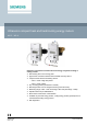
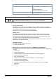
Ultrasonic compact heat and heat/cooling energy meters WS.5.., WS.6.. Ultrasonic heat meters to measure flow and energy in hydronic heating or cooling circuits. ● ● ● Non-wearing due to non-moving parts Approved in accordance with EN 1434 and MID accuracy class 2 Compact meter with flow measuring section – WS.5.. made of high-tech plastic ● ● ● ● ● ● ● CE2N5372en 2021-12-07 – WS.6..
Application The heat (WSM5../WSM6..) and cooling energy meters (WSB5../WSB6..) and combined heat/cooling energy meters (WSN5../WSN6..) are measuring devices to physically acquire energy consumption. The device consists of a flow measuring section made of high-tech plastic (WS.5..) or brass (WS.6..), 2 ready connected temperature sensors, and an electronic unit which calculates the energy consumption from the flow and temperature differential. The compact meter WS..
M-bus communication (optional) The meter can be read out from a remote location via an M-bus master unit, if the meter uses M-bus communication. M-bus RF communication (optional) If the meter uses M-bus RF communication, it can be read out remotely. Tampering To open the device, the calibration seal at the top of the WS.. must be destroyed. Self diagnostics The meter continuously performs self-diagnostics, allowing it to detect a number of mounting or device errors and to display them.
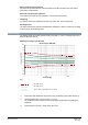
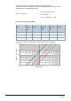
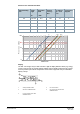
The pressure loss in a flow sensor is indicated as continuous flow qp. Actual pressure loss at the indicated flow can be calculated using the Kv value, which indicates flow at 1 bar differential pressure: Δp = Pressure loss in bar Δp = 1 bar x (Q / Kv) 2 Q = Flow in m3 / h Kv = Kv – Value at Δp = 1 bar Pressure loss characteristic WS.5.. Nominal flow qp Overall length m3/h Connecting thread Pressure loss at qp mbar Kv value at Δp = 1 bar m3/h Curve in the diagram mm 0.6 110 G¾ 75 2.2 A 1.
Pressure loss characteristic WS.6.. Nominal flow qp Overall length m3/h Connecting thread mm Pressure loss at qp mbar Curve in the diagram G / DN 0.6 110, 190 G¾ 150 1.5 A 1.5 130, 190 G1 160 3.8 B 1.5 110 G¾, 150 3.9 C 2.5 190 G1 210 5.3 D 2.5 130 G1 200 5.6 E A 1000 Pressure loss in mbar Kv value at Δp = 1 bar m3/h BC DE 250 100 10 0.1 1 10 Flow in m³/h Display The WS.. has a large, easy-to-read LCD with 7 digits to display different values (e.g.
The meter's display is subdivided into several loops. A short press on the button (<2 s) lets the current loop pass through line by line. The first line displays again after the last line. A long press (>3 s) displays the first line of the next loop. The first loop is displayed again after the last loop. The arrow icons mark the display of a stored value of the previous year or previous month. A calibrated value (e.g. energy) is marked on the display by a star symbol.
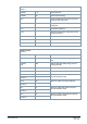
Current values LOOP 1 1234567 m3/h Current flow rate 1234567 kW Current thermal energy 80.0 °C Current temperature heat side at 2 second exchange with cooling side 50.0 °C Change with the current temperature with cooling side 21.0 K Temperature difference Mounting location (Here: Heat side, can be changed; optional) P hot Bd 1234 h Runtime totalizer Fd 123 h Error time Pd 1234 h Time with flow rate Monthly values LOOP 2 01.06.
General / Communication LOOP 3 1234567 Device number, 7 digits OMS RF standard (M-bus RF only) Unbind Meter not connected (M-bus RF only) Bind Meter connected (M-bus RF only) MbuS Interface (only for M-bus) 127A Primary address (only for M-bus) 0000000A Secondary address (only for M-bus) 01.01 Due date (yearly set day) 01.--.-- Monthly value (monthly set day) I 5-00 FW CrC 1234 Firmware version CRC code, part requiring calibration Other LOOP 4 17.11.11 Current date [DD.MM.YY] 10.38.
F7 Disruption of internal memory operation F8 F1, F2, F3, F5 or F6 persist longer than 8 hours Detection of tampering No further measurements are made F9 Error in the electronics NOTICE Manually reset message F8 in configuration mode or using the service software. All other error messages are deleted automatically as soon as the error is eliminated.
Type summary Cooling energy meter WSB.. is available upon request. Heat meters WSM and combined heat/cold meters WSN.. The types of meters listed below are equipped as follows: Mounting location In return Rated pressure PN 16 Length of control cable 1.5 m Sensor mounting Return sensor, integrated in the flow measuring section Sensor type Pt500, Ø 5.2 mm, length = 45 mm Temperature sensor cable length 1.
Heat meter continuous flow flow 1.5 m3/h with flow measuring section WSM5.. made of high-tech plastic.
Heat/cooling energy meter continuous flow 0.6 m3/h with flow measuring section WSN5.. made of high-tech plastic. Options Order number Type Mounting length 110 mm, connecting thread G ¾", Battery life 11-years, M-bus S55561-F278 WSN506-BE Mounting length 110 mm, connecting thread G ¾", Battery life 11-years, M-bus RF S55561-F281 WSN506-FE Heat/cooling energy meter continuous flow 1.5 m3/h with flow measuring section WSN5.. made of high-tech plastic.
Accessories Mounting accessories only for meters with high-tech plastic flow measuring sections: Accessories for WS.5.. Component Order number Type Flat seal G ¾" LYU:9060951 9060951 Flat seal G1" LYU:9060952 9060952 Mounting accessories only for meters with brass flow measuring sections: Accessories for WS.6.. Component Order number Type Sealing disk for thread G ¾" LYU:9060944002 9060944002 Sealing disk for thread G 1" LYU:9060944003 9060944003 Mounting set for sensor Ø 5.
Mounting kit 1", consisting of: 2x threaded connection G 1" x R ¾" 2x cap nuts G1" S55563-F123 WZM-E1 Adapter piece 110 mm G ¾" to 130 mm G ¾": 1x extension G ¾ B" to G ¾ B" 1x gasket G ¾" LYU:WZM-V130 WZM-V130 Adapter piece 110 mm G¾" to 130 mm G1": 2x extension G ¾ B" to G 1 B" 2x gaskets G 1" LYU:WZM-V130.G1 WZM-V130.
Ø 5.2x50 mm for temperature sensor Ø 5.2x45 mm, including gasket G ½", copper Protection pocket G ½ B made of stainless LYU:WZT-S43V steel, Ø 5.2x50 mm for temperature sensor Ø 5.2x45 mm, including gasket G ½", copper WZT-S43V Adapter kit, consisting of: - 1x plastic adapter Ø 5.2x45 mm - 1 mounting aid for sensor Ø 5.2x45 mm - 2 O-rings LYU:9956230 9956230 Spacer G ¾", length 110 mm, incl. 2 gaskets LYU:WZM-G110 WZM-G110 Spacer G 1", length 130 mm, incl.
Notes Mounting Flow measuring section The mounting orientation is optional, the mounting location (heat or cold side) must correspond to the meter type. On heat energy meters or combined heat/cooling energy meters, the mounting location of the cooling side corresponds to the return and the mounting location of the heating side to the flow . On cooling energy meters, the mounting location of the heating side corresponds to the return and the mounting location of the cooling side to the flow .
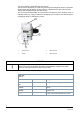
Required position for the cooling energy meter To avoid the formation of condensation on cooling energy or combined heat/cooling energy meters, make sure the cover on the measuring tube points to the side or downward. Install the protection pockets so that the temperature sensor is horizontal or vertical, pointing down. Mount the processor unit away from the flow measuring section (e.g. on the wall).
Wall mounting Wall adapter (view from above) Wall adapter (side view) Maximal screw head height (if using the wall bracket) Maintenance The meters are maintenance-free. Observe all national calibration regulations. Disposal The device is considered an electronic device for disposal in accordance with European Directive and may not be disposed of as domestic waste. ● Use only designated channels for disposing the devices. ● Comply with all local and currently applicable laws and regulations.
Technical data Processor unit Power supply Battery type Lithium battery (cannot be replaced) Battery voltage 3.6 V Battery life 6 or 11 years Function data Measuring range 0…180 °C Range of temperature differential ΔΘ 3 ... 80 K Temperature response threshold 0.2 K. Thermal coefficient Shifting compensated Temperature-measuring error without sensor (0.5 + ΔΘmin./ ΔΘ) %, Max. 1.5% at ΔΘ = 3 K Temperature sensor Sensing element Pt500 Type Ø 5.
Function data Pressure drop at qp ● Mounting length 110 mm Δp ● Mounting length 130 mm Δp mbar mbar 75 1) / 150 2) --- 135 1) / 150 2) --1) 2) 1) 135 / 160 165 / 200 2) 2.2 1) / 1.5 2) Flow rate at Δp = 1 bar, Kv, m3/h 4.11) / 3.9 2) Mounting position 6.81) / 5.6 2) Any 1) Plastic flow measuring section Brass flow measuring section 2) Communication Optical interface ● Basic design ● Protocol Similar to EN 62056-21 Per EN 13757-2 / -3 M-bus wired interface Optional ● Voltage Vmax.
Housing type Protection class Degree of protection ● Processor unit ● Flow measuring section III IP54 WS.5..: IP65 WSM6..: IP54 WSB6../WSN6..: IP65 Ambient conditions Operation Transportation Storage EN 60721-3-3 EN 60721-3-2 EN 60721-3-1 Climatic conditions Class A Class A Class A Temperature 5...55 °C -20...60 °C -20...60 °C Humidity <93 % r.h. at 25°°C (noncondensing) <93 % r.h. at 25°°C (noncondensing) <93 % r.h.
Housing material Cover Bottom section Battery compartment ABS PC-GF10 PC clear Housing colors Cover Bottom section RAL 9006 RAL 9002 Weight Device packed complete with inserts *) WSM506..: 0.52 kg WSM515..: 0.52 kg WSM525..: 0.56 kg WS.606..: 0.80 kg WS.615..: 0.76 kg WS.625..: 0.84 kg Documents can be downloaded at http://www.siemens.com/bt/download.
Connection diagram For meters with M-bus communication 1 Brown / white Dimensions WS.5..
WS.6.. Dimensions in mm Issued by Siemens Switzerland Ltd Smart Infrastructure Global Headquarters Theilerstrasse 1a CH-6300 Zug +41 58 724 2424 www.siemens.com/buildingtechnologies Document ID CE2N5372en Edition 2021-12-07 © Siemens Switzerland Ltd, 2012 Technical specifications and availability subject to change without notice.