
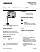
Installation Instructions

Document No. 563-002
Installation Instructions
January 12, 2007
24 V-AC
CEH
CH
DO 1 DO 2 DO 3 DO 4 DO 5
NO C NO C NO C NO C NO C
DO 6 DI 3 DI 2 FLN
TRUNK
NO C AI 3
TX RX + - S
BST RTS
1 2 3 4 5 6 7 8 9 10 11 12 13 14 15 16
1 2 3 4 5 6 7 8 9 10 11 12 13 14 15 16
WLAN0004R2
TEC Power
(From Transformer)
TEC
(Typical)
Channel
Network I.D.
24 Vac 1.2 VA
24 Vac
Power Line
Alternate
Power
3M Scotchlok
TM
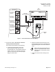
Power Connectors (Typical of 2)
1. Thread TEC power
wire through
connector.
2. Fold up flap to
lock TEC wire
into connector.
3. Insert power wire
from FLNX into
connector so it
appears in window.
4. Use lineman’s
pliers to pinch
connecting bar in
place and connect
wires internally.
5. Close connector
cover to secure
wires.
TEC
Power Wire
FLNX
Power Wire
Figure 4. FLNX Communication and Power Wiring.
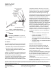
6. Connect the antenna. Be sure the antenna is
securely connected to the FLX.
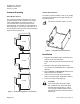
For a remote mount antenna, do the following:
a. Locate the liquid tight fitting so that the
antenna extension cable does not incur
excessive p ull force. At t he desired en clo s u re
location, punch a 1/2” knockout and use the
locknut to secure the body of the liquid tight
fitting into the knockout.
b. Route the antenna through the body of the
liquid tigh t fitting (Figure 5). Hand-tig hten the
liquid tigh t fitting nut to secure the antenna in
place.
Make certain the liquid tight fitting nut
tightens on the antenna base, not the
antenna itself, s o the antenna can be
articulate d.
c. Connect the antenna wire securely to the
FLNX.
Siemens Building Technologies, Inc. Page 3 of 4