
Installation Instructions

Document No. 563-002
Installation Inst ructions
January 12, 2007
Antenna Mounting
Direct Mount Antenna
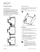
The preferred mounting configuration is to mount
the FLNX outside the TEC enclosure in a location
where it will estab lish t he maximum number of
communication links with other FLNXs and its
associated FPX. For example, in a VAV application
this will typically be on the bottom of t he VAV box in
the ceiling plenum with the entire antenna extending
below the VAV box (Figure 2).
WLAN0017R2
VAV BOX
VAV BOX
VAV BOX
Figure 2. FLNX Mounting Options – No Enclosure.
Remote Mount Antenna
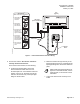
The FLNX is mounted inside the TEC (or any metal)
enclosure and the antenna is brought through a 1/2”
knockout (Figure 3).
The antenna extension cable is 12” long.
WLAN0016R1
Figure 3. FLNX Mounted Inside Enclosure.
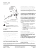
Installation
1. Determine the optimal location of the FLNX and
antenna for RF communications.
Ideally, the antenna should extend below the VAV
box.
2. Mount t he FLNX using the provided screws.
You can also us e dou ble -sid ed tap e or VEL CRO
®
fasteners.
3. Set the Channel and Network ID switches to the
settings selected for the WFLN.
4. Connect the communication port of the FLN
device to the FLNX (cable length limit is 4000 ft).
5. Connect to 24
Vac p ower (F igure 4).
CAUTION:
If the FLNX shares the power supply
with a Wirele ss TEC Transceiver (TTX,
P/N 550-205) and the TEC, be sure to
useagroundisolatedtransformer(P/N
550-710) between the TTX and the power
transformer.
Page 2 of 4 Siemens Building Technologies, Inc.