
User Manual


5/8
Siemens Building Technologies Product data sheet WFT10 CE1N5440E
Landis & Staefa Division 07.07.1999
•
Local regulations for water meters (installation, operation, etc.) should be observed.
•
It is recommended to thoroughly clean the pipe before installing the WFT10.
•
The volume indicator can be installed in a horizontal or vertical position.
•
Observe the flow direction indicated by the arrow on the volume indicator.
•
The housing should be installed horizontally at eye level so that one can easily read
the LCD display and easily reach the controls.
•
Ensure that the volume indicator and shutoff valve are not too far from the control unit
so that the lengths of the cables provided are sufficient.
•
In order to be able to switch off all power, it is recommended to install an external
switch in front of the electronic unit.
•
Local regulations for valves (installation, operation, etc.) should be observed.
•
The WFT10 should be connected as directly as possible to the main water supply,
but in no case in front of the main water meter.
•
The control panel’s position can be chosen freely. However, an installation with verti-
cal electric motor is preferable.
•
Ensure that the valve’s manual lever is freely movable and easily accessible.
The enclosed installation instructions should be followed.
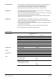
Technical Data
Nominal Flow q
p
=
1.5 m
3
/h 2.5 m
3
/h
Position optional optional
Maximum flow rate q
s
= 3 m
3
/h q
s
= 5 m
3
/h
Passivity q
a
= ca. 3 l/h q
a
= ca. 5 l/h
Nominal pressure PN = 10 bar PN = 10 bar
Pressure drop at q
p
< 250 mbar < 250 mbar
Pressure drop at q
s
< 1 bar < 3 bar
Max. median temperature +90 °C +90 °C
Connection external thread G1 external thread G1
Operating voltage AC 230 V
Max. operating current 10 mA
Housing Dimensions without cable glands
LxWxH = 185 x 213 x 104.5 mm
3
International protection IP65
Relay Outputs Switching voltage
AC 230 V
Operating life at nominal load > 50.000 switchings
Switching power supply 1 A
Inputs Pulse input volume detector
Max. input voltage
Input resistance
5 V
150 k
Ω
Inputs for feedback, alarm, and OFF contact
Contact rating max. voltage
Contact rating max. current
5 V
20 mA
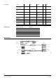
Volume Indicator
Control Unit
Shutoff Valve
Volume Detector
Control Unitc