
User Manual


4/8
Siemens Building Technologies Product data sheet WFT10 CE1N5440E
Landis & Staefa Division 07.07.1999
General Features
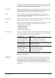
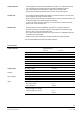
The WFT10 housing is made of plastic and is attached to the wall with three screws. It
includes a service part with hinged lid as well as a clamp box.
1: RS232-Schnittstelle
2: Display
3: Kabelverschraubung
4: Klemmraumabdeckung
5: Tastenfeld
34
5
21
12
3
45
5440Z02
1 RSR232 interface
2 Display
3 cable glands
4 Clamp box cover
5 Button board
The service part is made accessible by opening the transparent lid. It includes four
buttons, the LCD display, and the RS232 interface.
Seven cable glands are available for installing the connecting cables. Opening the
cover provides access to the terminal clamps. The clamps can be removed from their
connector strips for wiring.
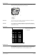
Characteristics
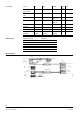
Pressure loss characteristics
∆
p Pressure loss in bar
∆
0,5
0,4
0,3
0,25
0,2
0,1
0,05
0,04
0,03
0,02
0,01
1,0
0,2 0,3 0,40,5 1,0 1,5 2 3 4 5
Q
p
5440D01
q
p
= 1,5 m
3
/h q
p
= 2,5 m
3
/h
q Flow rate in m
3
/h
Installation Notes
The WATERBRAKE system required a fixed connection to the existing electrical net-
work. The network must conform to the norm DIN 57 100 part 410 or VDE 0100 part
410 and others. The installation work is to be done by qualified personnel.
Service Part
Clamp Box