
User Manual


3/8
Siemens Building Technologies Product data sheet WFT10 CE1N5440E
Landis & Staefa Division 07.07.1999
ning device connected to the signal output. If a limit is reached, an alarm is triggered
and the shutoff valve closes. A message appears in the display, and optionally you can
get a visual or acoustic signal by a external warning device.
Only authorized service personnel can set the limits of the control criteria. This can be
done on the device itself or with a PC via the RS232 interface, and the limits are sepa-
rately adjustable for each day of the week as well as for night and day.
An input is available for receiving alarm signals triggered by an external device.
There is another input for connecting an additional OFF switch. Both inputs can be
connected to floating potential switches.
Floating potential outputs are available for both the alarm and warning message. Both
outputs can switch a voltage of AC 230 V and a current of AC 1 A.
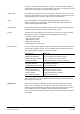
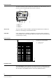
The device’s standard display is the current flow rate, as long as no alarm or warning
messages are activated. In addition, the following displays can be chosen:
•
Current flow volume and duration
•
Day of the week and time
•
Beginning of day mode
•
Beginning of night mode
•
Normal operation / holiday mode
The control unit monitors compliance with the set limits as well as the functioning of the
valve and the temperature sensor. It can also display detected deviations and errors.
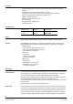
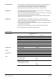
The following warning and alarm messages are possible:
Error Message
Explanation
“FLOW RATE WARNING” 80 % of maximum flow rate reached
“DURATION WARNING” 80 % of maximum flow duration reached
“FLOW VOLUME WARNING” 80 % of maximum flow volume reached
“FROST WARNING” Temperature dropped to 3 K above minimum
“VALVE ERROR” Missing valve feedback
“BATTERY ERROR” Buffer battery exhausted
“TEMPERATURE SENSOR” Defective sensor cable
“FLOW RATE ALARM” Maximum flow rate reached
“DURATION ALARM”
Maximum flow duration reached
“FLOW VOLUME ALARM” Maximum flow volume reached
“FROST ALARM” Temperature dropped to minimum
“EXT. SENSOR ALARM” Alarm by external sensor
With a connected PC, the last 30 warning and alarm messages as well as the current
limit settings can be read out.
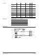
The ball valve is directly controlled by an electric motor with downstream reduction
gear. In case of malfunction, the valve also has a manual operating mode. The two
additional end-position-switches for feedback enable communication with the control
unit. In addition, the device is equipped with a visual Open/Closed indicator.
In case of alarm, the shutoff valve requires about 90 seconds to completely disrupt the
water supply.
Setting Limits
Inputs
Signal Outputs
Display
Error Messages
Shutoff Valve