Metering Impeller type heat and heat/cooling energy meters WFx5 Electronic, mains-independent impeller type heat meters with optional cooling range to acquire heat or cooling energy consumption on autonomous heating, cooling or solar plants. ● ● ● ● ● ● ● CE2N5323_en--_b 2018-01-23 Nominal flow 0.6 m3/h, 1.5 m3/h or 2.
Use The impeller type heat and cooling energy meter is of compact design and used for the physically accurate acquisition of energy consumption. The meter consists of a flow measuring section, 2 ready connected temperature sensors, and an electronic unit which calculates energy consumption from the flow and the temperature differential. The device is available for heat, combined heat/cooling, or solar metering.
Processor The same standard processor with a built-in service unit is used for all flow rates. Infrared interface Consumption meters with optical close-range interface must be read out on site. The meter is read out and configured with the WFZ.IRDA-USB optical reading head and the associated ACT50 software. Module interface Each meter is equipped with a module interface. The meter can be read out from a remote location by installing the optional add-on module.
Technical design Screwed type meter Pressure loss characteristics 0.6 m3/h, 110 mm ?p (bar) 1 0.5 0.4 0.3 0.2 0.1 0.05 0.04 0.03 0.02 0.01 0.01 Screwed type meter Pressure loss characteristics 1.5 m3/h, 80 mm and 110 mm 0.02 0.03 0.05 0.1 0.2 0.3 0.5 1 2 q (m3/h) Δp (bar) 1 0.5 0.4 0.3 0.2 0.1 0.05 0.04 0.03 0.02 0.01 Screwed type meter Pressure loss characteristics 2.5 m3/h, 130 mm 0 0.1 0.2 0.3 0.5 1 2 3 4 5 0.1 0.2 0.3 0.5 1 2 3 4 5 q (m3 /h) Δp (bar) 1 0.5 0.4 0.3 0.
Parameter settings via PC The following parameters are read out or set with the ACT50 software via the optical closerange interface: General ● Serial number ● Mounting place ● Installation location ● Firmware version ● Medium ● Date of commissioning ● Battery life ● Stock number ● Heat carrier ● Error date ● Error code Device information ● Current temperature (return) ● Current temperature (flow) ● Current temperature (difference) ● Current energy flow ● Current flow rate ● Total flow rate ● Pulse value ● D
Parameter settings via the meter The following parameters can be entered directly on the meter using both operating buttons: ● Next due date ● Display of kWh or MWh/MJ or GJ ● Selection of levels to be displayed ● Display of meter read outs with or without checksum In addition for devices with solar modification: ● Ratio of glycol on solar plants Communication The meter is supplied with an optical close-range interface.
● Current consumption values (heat or cooling energy, volume) ● Due date ● Due date value (heating or cooling energy) The following data queried via application selection (per EN 13757-3 or supplier-specific) as an option: ● 13 monthly values (heating or cooling energy) ● Flow rate ● Power ● Energy ● Flow/return temperature RF add-on module WFZ662 The meters are read out remotely using the RF add-on module. The module sends out parallel AMR and walk-by data telegrams.
RF settings ● RF mode ● RF system ● Walk-by readout type ● Walk-by transmission delay ● Walk-by transmission timeframe ● Walk-by transmission-free days Configuration: General ● Mounting place Due date ● Next due date Device information ● Device name ● Device password RF settings ● RF mode ● RF system ● Walk-by readout type (S-mode only) ● Walk-by transmission delay (S-mode only) ● Walk-by transmission timeframe ● Walk-by transmission-free days (S-mode only) RF features in S-mode RF add-on module in S-mode h
Transmission response Transmission-free Monthly: Saturday and Sunday days Annually: Sunday Current consumption value, due date value, due date as well as end of month values for the last 13 months RF features in C-mode RF add-on modules in C-mode have the following features: RF system Parallel transmission of data telegrams ● ● AMR Walk-by Increase RF output (typically 10 dBm) AMR telegrams Every 7.
Operating Quick reading mode The meter's display is in sleep mode and only activates when a button is pressed. A single short press of a button repeats the quick read loop 10x. At the end of 10 repetitions, the display returns to sleep mode . Current value 5 sec. Display test - all off 0.5 sec. 10x Display test - all on 0.5 sec. Current due date 5 sec. Due date value 5 sec. pulsing The quick read loop can be cancelled at any time by pressing a button > 3 s.
Error messages For a serious fault, the error code and error data is displayed in front of the meter state display.
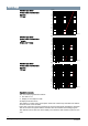
Level L0 Current consumption values Displays the level ytest – all on Display test – all off Error code Error date al t. Current meter status Current consumption values These segment blocks depend on the device. configuration This display only appears when a device fault has occurred a lt . Serial number Current date Checksum WMZ a lt . alt . a lt . alt . alt . KMZ a lt . alt . alt . IMP1 a lt . alt . alt . IMP2 alt .
Level L3 Parameters Displays the level Date of ref. due date Impuls value VMT Calibration Firmware version Identification Calibration checksum Firmware version a lt . Possible + activated levels Fabrication no. a lt . This example: __ (space) = level 6 hidden = level 7+8 not available These segments appear depending on the device configuration.
Level L6 Monthly values cooling energy This level is displayed only when the meter is configured for metering cooling energy. Checksum alt. alt. alt. alt. Serial number alt. Checksum Serial number alt. The displays coloured grey are optional or can be added and switched off as required. Level L9 Maximum values Displays the level Maximum values Supply flow temperature Date of highest temperature Highest temperature Maximum values Return flow temperature al t. a lt. al t. a lt.
Indication of errors Description of error Measures/notes Flow sensor short circuit Check the temperature sensor and wires for mechanical damage Exchange the device Return sensor is broker Check the temperature sensor and wires for mechanical damage Exchange the device Return sensor short circuit Check the temperature sensor and wires for mechanical damage Exchange the device Description Measures/notes Exceeds communications credit IrDA Eliminated after credit period expires (Irda = current month
Display Description Displayed value is a checksum: Check = Checksum refers to a current consumption value M-Check = Checksum applies to a saved yearly or monthly value Current flow available No energy metering -> No temperature difference Current flow available Energy metering IrDA communication is just active Processor The meter's processor is designed as follows: 7 4 8 3 2 6 5 1 1 LCD 5 Interface cover 2 Button to change between levels 6 Module interface 3 Button to navigate on a level 7
Wireless meters ACT50 is used to configure the wireless modules. Wireless operation is activated via the WFZ-PS radio telegram tool or the ACT50 software. Wired meters Since the M-bus module adopts all parameters from the meter, only the primary address can be configured via the M-bus system. The power required for operation is supplied by the M-bus system, but the module is equipped with a battery. It powers the module when there is no power available from the Mbus.
Combined heat/cooling energy meters and additional types available on request. Add-on modules Designation Order number Type M-bus module S55563-F131 WFZ51 RF add-on module S55563-F153 WFZ662 Designation Order number Type Installation set Rp ½", consisting of: 2 ball valves Rp ½" with coupling nut G ¾" and flat gasket 2 mm, ¾" 1 ball valve Rp ½" with M10x1 mm for fitting temperature sensor Ø5.
Installation sets fittings Building Technologies Designation Order number Type Installation set Rp ½", consisting of: 2 fittings Rp½" with coupling nut G¾" and flat gasket 2 mm, ¾" 1 ball valve Rp ½" with M10x1 mm for fitting temperature sensor Ø5.0x45 mm JXF:HMXIK002-001 HMXIK002-001 Installation set Rp ¾", JXF:HMXIK002-002 consisting of: 2 fittings Rp ¾" with coupling nut G ¾" and flat gasket 2 mm, ¾" 1 ball valve Rp ¾" with M10x1 mm for fitting temperature sensor Ø5.
Spacers Designation Order number Type Spacer G ¾", Length 80 mm JXF:FKM0070 FKM0070 Spacer G ¾", Length 110 mm JXF:FKM0074 FKM0074 Spacer G 1", Length 130 mm JXF:FKM0075 FKM0075 Designation Order number Type Adapter set G ¾" to 1", consisting of: 2 adapter pieces G ¾" to G 1" 2 flat gaskets 2 mm, 1" JXF:HMXIK003-001 HMXIK003-001 Extension set G ¾" x G 1", consisting of: 2 extension set from 110 mm, G ¾" to 130 mm G 1" 2 flat gaskets 2 mm, 1" JXF:HMXIK003-002 HMXIK003-002 Extension set 1
Fittings Designation Order number Type Fittings R ½" x G ¾", without gasket JXF:FKM0018 FKM0018 Fittings R ¾" x G ¾", without gasket JXF:FKM0019 FKM0019 Fittings R 1" x G ¾", without gasket JXF:FKM0020 FKM0020 Fittings R ¾" x G 1", without gasket JXF:FKM0021 FKM0021 Fittings R 1" x G 1", without gasket JXF:FKM0022 FKM0022 Designation Order number Type Ball valve Rp ½" with temperature sensor fitting M10x1 mm for sensor Ø5.
Accessories Designation Order number Type Flat gasket ¾", thickness 2 mm JXF:FKS0005 FKS0005 Flat gasket 1", thickness 2 mm JXF:FKS0006 FKS0006 T-piece R ½" x G ¼" JXF:FKM0035 FKM0035 T-piece R ¾" x G ¼" JXF:FKM0036 FKM0036 T-piece R 1" x G ¼" JXF:FKM0037 FKM0037 Immersion sleeve G ¼" for sensor Ø5.0 x 45 mm, without gasket JXF:FKM0038 FKM0038 Immersion sleeve M10x1 mm JXF:FKM0051 for sensor Ø5.0x45 mm, without gasket FKM0051 Immersion sleeve G ¼" for sensor Ø5.
Ordering When ordering, please specify the quantity, designation, type, and order number. Designation Order number Type Impeller heat and heat/ cooling energy meter See "Type overview" WFx5.. Scope of delivery The meters come complete with operating and installation instructions in different languages as well as all required mounting materials (gaskets, seals, etc.). The RF add-on module is delivered in packages of 10 items (1 packaging unit).
Maintenance The meters are maintenance-free. Comply with all national calibration regulations. Disposal The device is considered an electronic device for disposal in accordance with the European Guidelines and may not be disposed of as domestic garbage. ● Dispose of the device through channels provided for this purpose. ● Comply with all local and currently applicable laws and regulations. ● Dispose of empty batteries in designated collection points.
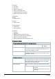
Technical data Processor Power supply Battery type Lithium battery CR AA (cannot be replaced) Battery power 3.0 V Battery life 10 years with reserve Function data Measuring range ● ● Heat meter Heat meter with optional cooling range 15...105 °C Cooling range: 0.2...24 °C Range of temperature differential ΔΘ 3...70 K Temperature response threshold ● ● Heating Cooling 1.0 K 0.2 K Thermal coefficient Shifting-compensated Temperature sensor.
Flow measuring section Screw type meter Pressure loss at qp ● Mounting length 80 mm Δp ● Mounting length 110 mm Δp ● Mounting length 130 mm Δp mbar mbar mbar 200 Flow rate at Δp = 1 bar, kv m3/h 1,5 200 200 180 Mounting orientation 3,2 3,2 5,3 Horizontal/vertical Communication M-bus module WFZ51 M-bus slave interface As per EN 1434-3 and EN 13757-2/3 ● ● ● ● ● ● ● ● ● ● ● Lithium battery CR 2/3 AA DC 3.0 V ≤1.5 mA 1.5 mA Primary and secondary 300 or 2,400 baud Optional Per module interface 2.
Standards, guidelines EU Conformity (CE) ● ● ● Processor Radio module M-bus module CE2T5323xx *) CE2T5323xx01 *) CE2T5323xx02 *) Heating media quality VDI guideline 2035 Type approval as per EN 1434-4 Environment class A Measuring accuracy class 3 Product standards DIN EN 1434-1 (heat meters) Environmental compatibility Product environmental declaration CE1E5323en*) contains data on environmental-compatible product design and assessment (RoHS compliance, compositions, packaging, environmental benef
Dimensions Screwed type meter 64.3 50.3 Mounting length 80 mm Mounting length 110 mm 80 101.5 68.7 52.1 66.3 50.3 Mounting length 130 mm 78 130 Dimensions in mm Add-on modules Dimensions in mm Issued by Siemens Switzerland Ltd Building Technologies Division International Headquarters Gubelstrasse 22 CH-6300 Zug Tel. +41 58 724 2424 www.siemens.