
User Manual

3/4
Siemens Building Technologies CE1N2147en
Landis & Staefa Division 26.01.2000
Engineering notes
The valves come pre-adjusted or with a flow limitation by means of stroke limitation.
Pre-adjustment facilitates proper hydraulic balancing of the system, which means that
the radiator always will receive the right amount of water.
Mounting notes
The threads are coated with stop-“drop“ sealing compound, facilitating straightforward
fitting with no need for additional sealing materials.
Installation notes
•
Observe the installation choices and conditions to ensure the thermostatic heads will
function correctly
•
Allow room air to freely circulate around the sensor
•
The sensor may not be exposed to direct solar radiation
•
The valves should be installed horizontally whenever possible
•
When removing the radiators, remove the protective cover from the changeover valve
and use an Allen key to turn the screw until the stop is reached, thus shutting down
the return. The adjustment can also be used to limit the return flow. The flow is closed
by the thermostatic valve
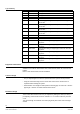
Technical data
Flow temperature 2 °C to max.110 °C
Operating pressure max. 10 bar
Closing pressure max.1.5 bar
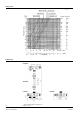
Differential pressure 0.01-0.06 bar (recommended range)
Material of valve body brass Cu Zn 40 Pb2
Material of tailpiece brass Cu Zn 40 Pb2
Radiator connection R1/2”
Max. flow rate 1.4 m
3
/h
Surface nickel-plated
Tailpiece nickel-plated, with “stop-drop“ seal and O-ring
Protective cover polypropylene
Length DIN 3841
Thread DIN 2999
Medium heating water with max. 40 % ethylene-glycol
General data