
Data Sheet for Product

3
Siemens A6V11877580_en--_c
Smart Infrastructure 2020-10-08
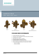
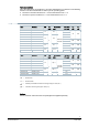
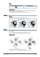
A Inlet medium (inlet port)
B Outlet medium (outlet port)
2 Ring with dial for presetting
4 Differential pressure controller maintains the
pressure P1 – P2 constant across the presetting
[5]
6 On/Off control valve with mounted actuator
P1 Pressure at inlet of PICV
P2 Pressure at outlet of presetting
P3 Pressure at outlet of PICV
P+ P/T port, pressure test point with red ribbon [7]
P- P/T port, pressure test point with blue ribbon [6]
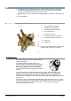
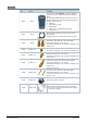
Manual control
The manual control knob can be fitted to protect the valve stem and
facilitates manual control of the PICV during commissioning. The
manual control knob is delivered loose in the box.
Factory setting:
The valve is open. To close the valve, turn the manual knob clockwise.
The valve must be open to purge the system.
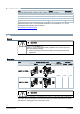
Sizing
Engineering example
Basis of calculation
1. Determine energy demand Q [kW]
2. Determine temperature differential (supply – return) ΔT [K]
3. Calculate volumetric flow
Hint: you can also determine the volumetric flow using the valve slide rule.
4. Select suitable PICV
– Pipe connections (internally or externally threaded)
– With or without P/T ports
– Ideally, PICVs should be selected such that they operate at about 80 % of their
maximum flow, enabling them to deliver spare capacity, if required.
a Determine dial setting using volumetric flow/dial presetting table, cf. Volumetric flow/dial
presetting [➙ 4]
Example
w Given is a heat exchanger with:
1. Energy demand: Q = 1.9 kW
2. Temperature differential: ΔT = 6 K
3. Volumetric flow: