
Data Sheet for Product

2
Siemens A6V11877580_en--_c
Smart Infrastructure 2020-10-08
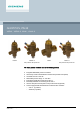
Use
● In ventilation and air conditioning plants for control on the water side and automatic
hydraulic balancing of terminal units, such as fan coils, induction units, and in heat
exchangers for heating and cooling, with 2-point control
● In heating zones, such as self-contained heating systems, apartments, individual rooms,
etc.
● For closed circuits
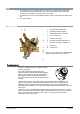
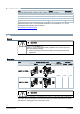
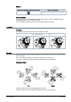
Technical design
1 Ring with dial for presetting
2 Variable presetting opening
3 Differential pressure controller
4 Flow control valve
5 On/Off control valve
6 Pressure test point, blue ribbon, P-
7 Pressure test point, red ribbon, P+
A Inlet port A
B Outlet port B
PICV VQ..46..Q (shown here) is additionally
equipped with pressure test points P/T.
Functional principle
The above drawing is used as a reference for this
following description.
The medium entering the valve (inlet port A)
passes through the variable presetting opening [2]
which is connected to the ring with the dial [1] for
presetting the desired maximum volumetric flow.
Then, the medium flows through the On/Off control
valve [5].
The actuator opens and closes the On/Off control valve [5]. After the presetting, the
medium passes through a built-in mechanical differential pressure controller [3]. This
differential pressure controller is the heart of the PICV and ensures that the selected
volumetric flow is maintained across the whole working range and independent of the inlet
pressure P1.
The PICV VQ..46..Q are additionally equipped with 2 pressure test points (P+, P-). These
pressure test points allow the measurement of the differential pressure across the PICV in
order to check if the Δp is sufficient to reach Δp
min
. For that purpose, the electronic
manometer ALE10 can be used.