
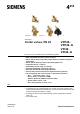
Data Sheet for Product

7 / 17
Siemens Combi valves, PN 25 CE1N4855en
Smart Infrastructure 2020-10-19
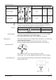
Sizing
Basis of calculation
1. Determine energy demand Q [kW]
2. Determine temperature differential ΔT [K]
3. Calculate volumetric flow
v
=
Q
[
kW
]
∙ 1000
1,163 ∙ ∆T
[
K
]
l
h
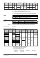
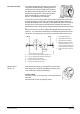
4. Select suitable Combi valve
- pipe connections (internally or externally threaded)
- with or without P/T ports
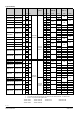
5. Determine dial setting using volumetric flow/dial presetting table, see the follow-
ing page
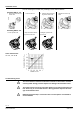
1. Given is a heat exchanger with Q = 1.9 kW
2. Temperature differential (supply - return) ∆T = 6 K
3. Volumetric flow
v
=
1,9kW ∙ 1000
1,163 ∙ 6 K
= 272,28 h
⁄
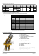
Hint: You can also determine the volumetric flow using the valve slide rule.
4. The valve shall have connections with external threads to ISO 228-1 and size
DN 15.
5. Combi valve selection:
Ideally, Combi valves should be selected such that they operate at about 80%
of their maximum flow, enabling them to deliver spare capacity, if required.
VPP46.15L0.6 (externally threaded connections, no pressure test points P/T,
nominal volumetric flow 600 l/h)
6. Determine dial setting using volumetric flow/dial presetting table below:
Volumetric flow 270 l/h
Dial setting 1.8
Engineering example
Example