
Data Sheet for Product

5 / 17
Siemens Combi valves, PN 25 CE1N4855en
Smart Infrastructure 2020-10-19
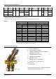
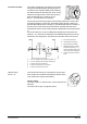
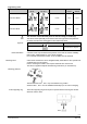
The medium entering the valve (inlet port A) passes
through the variable presetting opening (5) which is
connected to the ring with the dial (2) for presetting
the desired maximum volumetric flow. Then, the me-
dium flows through the flow control valve (6) with a
linear characteristic and a stroke of 2.5 mm
(DN 10…15) respectively 5 mm (DN 20).
Ring with dial for presetting (2)
The actuator (not shown here) opens and accurately positions the control valve
(6). Before leaving the Combi valve, the medium passes through a built-in me-
chanical differential pressure controller (4). This differential pressure controller is
the heart of the Combi valve and ensures that the selected volumetric flow is
maintained across the whole working range and independent of the inlet pressure
p
1
.
The Combi valves VP..46..Q are additionally equipped with two pressure test
points (P+, P-), which allow measurement of the differential pressure across the
Combi valve. For that purpose, the electronic manometer ALE10 can be used.
A Inlet medium (inlet port)
B Outlet medium (outlet port)
2 Ring with dial for presetting
4 Differential pressure controller
maintains the pressure p
1
– p
2
constant across the flow control
valve (6) and the presetting (2)
6 Control valve with mounted ac-
tuator
P- = P/T port, pressure test point with blue ribbon (7)
P+ = P/T port, pressure test point with red ribbon (8)
p
1
= pressure at inlet of Combi valve
p
2
= pressure at outlet of flow control valve
p
3
= pressure at outlet of Combi valve
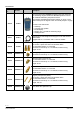
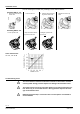
The manual control knob (1) is ready fitted to protect valve
stem and pre-set mechanism and facilitates manual control
of the Combi valve during commissioning.
Factory setting:
The valve is open. To close the valve, turn the manual knob
clockwise.
The valve must be open to purge the system.
Functional principle
Manual control
DN 10…32