
Installation Instructions
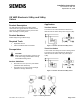
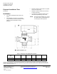
Table Of Contents

Document No. 129-174
Installation Instructions
September 25, 2009
Information in this publication is based on current specifications. The company reserves the right to make changes in specifications and
models as design improvements are introduced. Product or company names mentioned herein may be the trademarks of their respective
owners.© 2009 Siemens Industry, Inc.
Siemens Industry, Inc.
Building Technologies Division
1000 Deerfield Parkway
Buffalo Grove, IL 60089-4513
U.S.A.
Tel. +1 847-215-1000
Your feedback is important to us. If you have
comments about this document, please send
them to sbt_technical.editor.us.sbt@siemens.com
Document No. 129-174.
Printed in the U.S.A.
Page 2 of 2
Expected Installation Time
22 Minutes
Installation
• The valve assembly should mount in the
return.
• The assembly can mount in any position
except with the actuator beneath the valve.
Figure 1 shows allowable mounting
positions.
• Match the direction of flow with the symbol
cast on the valve body.
• Minimum clearance above the actuator is
4 inches (100 mm).
• The valve has a protective plastic cap to
allow manual positioning of the valve.
NOTE: Do not discard the plastic cap. It may
be needed during troubleshooting or
for emergency valve operation.
Table 1. Dimensions of the VMP Valve Assembly.
Nominal Valve
Size
Inches (mm)
A B B* C D E
1/2 (15)
3-5/16 (84)
1-3/8 (35)
1-11/16 (42)
1/2” NPT
15/16 (24)
3-1/2 (89)
3/4 (20)
4 (100)
1-5/8 (41)
1-7/8 (48)
3/4” NPT
1-3/16 (30)
3-5/8 (92)