
Data Sheet for Product


3/8
Siemens Small Valves CE1N2103en
Smart Infrastructure 2020-10-06
Engineering notes
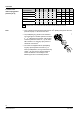
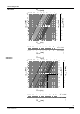
The reference numbers for preadjustment are given in the table with the k
v
-values (see
page 3) and in the valve sizing charts (see page 4).
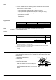
1.
Calculate the volumetric water flow
100
V
&
1
100
100
fT1.163
Q
.
V
´D´
= [m
3
/h]
Q
100
= heat/refrigeration demand [kW]
ΔT = temperature differential [K]
1.163 = constant of water
f
1
= correction factor = 1 for water
2.
Define the pressure drop
Δ
p
v100
across th
e fully open valve
In most types of plant, a differential pressure Δp
v100
of 0.05 to 0.2 bar is adequate
(5
to
20 kPa)
.
3.
Calculation of the nominal flow value k
v
100v
100
v
Δp
V
k
&
= [m
3
/h]
Δp
v100
= pressure drop across the valve [bar]
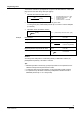
Heat demand
Q
100
=
4
.
7 kW
Temperature differential
ΔT
= 8 K
Volumetric water flow
81.163
4.7
V
.
100
´
=
= 0.51 m
3
/h (510 l/h)
Required pressure drop across the valve
Δp
v100
= 0
.
1 bar
Flow
0.1
0.51
kv =
= 1.61 m
3
/h
Solution
According to the chart (refer to « Valve sizing charts») or table with k
v
-values, the
preadjustment required by a VD120CLC valve is 6.
Tips
· Noiseless operation is ensured by a pump that provides no more pressure than is
needed to transport the required amount of water.
· To keep the valve free from dirt particles, it is recommended to install a strainer.
· If no pressure drop calculation is executed, preadjustment should be set with a
differential pressure Δp
v100
of 0.1 bar (10 kPa).
Example: