
User Manual


6/8
Siemens VBG31.. Three-port slipper valves PN10 CM1N4233en_g
Building Technologies 2018-11-30
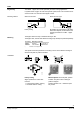
Dimensions
All dimensions in mm
D
AA
A
DN
M
N
4233M02
C
B
BB
G
H
J*
K**
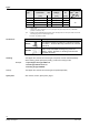
Type DN A AA B BB C D G H J* K** M N Weight
[Inch] [Inch] [kg]
VBG31.20 20 Rp ¾ 110 162 55 81 G 1¼B 12 24.5 74 46 34 32 48 1.9
VBG31.25 25 Rp 1 110 168 55 84 G 1½B 14 24.5 74 46 34 38 48 2.2
VBG31.32 32 Rp 1¼ 130 195 65 97.5 G 2B 14 42.5 81.5 53.5 41.5 47 67 3.5
VBG31.40 40 Rp 1½ 130 198 65 99 G 2¼B 16 42.5 81.5 53.5 41.5 53 73 3.8
DN = Nominal size
J* = Installation height of actuators SQK34.00 or SQK84 (without mounting kit)
K ** = Installation height of actuators SQK33.00, SQL33.... or SQL83.00 with ASK32 mounting kit
of actuators SAL..T10 with mounting kit ASK32N
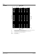
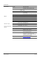
= Installation height of three-port slipper valve
+ Installation height of mounting kit (if used)
+ Installation height of actuator
+ Minimum clearance (> 200 mm) from ceiling or wall for mounting, connection, operation, service etc.
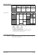
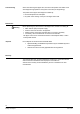
Spare parts
Order number for spare parts
manual adjuster
3-port slipper valve
VBG31.20
7467601750
VBG31.25
VBG31.32
VBG31.40
Overall height of slipper
valve and actuator
Issued by
Siemens Switzerland Ltd
Building Technologies Division
International Headquarters
Theilerstrasse 1a
6300 Zug
Switzerland
Tel. +41 58-724 24 24
www.siemens.com/buildingtechnologies
© Siemens Switzerland Ltd, 2008
Technical specifications and availability subject to change without notice.