
Data Sheet for Product


2/8
Siemens VBF21.. 3-port slipper valves PN6 CM1N4241en_d
Building Technologies 2018-11-30
Notes
Use the VBF21.. in mixing applications.
In systems where oxygen can enter the hydraulic system, there is an increased risk of
corrosion which can cause the valve slipper to seize.
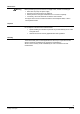
Boiler flow from left Boiler flow from right
4232H01
4232H02
Factory setting Re-position the valve slipper, scale plate
and manual adjuster (DN 40 and DN 50),
as described in the mounting instructions.
The slipper valves are easy to assemble directly on site.
The slipper valve, actuator and mounting kit (with mounting instruction) are packed
separately.
Mounting instructions for O-Ring replacement: M4241
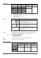
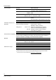
Accessory Mounting instruction
ASK31N M4502.1 74 319 0739 0
ASK32
1)
M4290.2 4 319 5597 0
ASK32N A6V11558817 A5W00057302
1)
ab 2019: nur solange Vorrat
Two special screws are provided in the housing cover to fix the ASK32 mounting kit
and the scale plate for position indication. The ASK32N kit contain all the components
required for assembly.
The ASK31N kit contain all the components required for assembly.
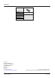
4299Z16
4299Z28
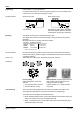
Factory setting
Slipper positioned for "boiler flow
from left".
· Anti-clockwise rotation: opening
· Clockwise rotation: closing.
Manual adjuster for DN40 / DN50 with scale
plate, position indicator and yellow color
marking for position of slipper
Position indicator at "0" = boiler flow path
fully closed.
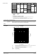
When commissioning the slipper valve, ensure that the position and rotation of the
valve slipper are appropriate for the system concerned (see "Engineering").
The position of the valve slipper is indicated as follows:
· DN 40 and DN 50 slipper valves: by the manual adjuster and scale plate and by the
yellow color marking on the pin in the slipper valve shaft
· DN 65…150 slipper valves: by a red plastic marker (part of the mounting kit) which
is fitted to the slipper valve shaft.
Engineering
Mounting variants
Mounting
DN 40 and DN 50
DN 65...150
Orientation
Commissioning