
Data Sheet for Product


3/8
Siemens VBF21.. Dreiweghähne PN6 CM1N4241en_d
Building Technologies 2018-11-30
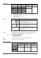
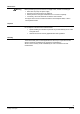
Type
Actuator
type
Operating
voltage
Positioning
signal
Positioning
time for 90°
Torque
Data
sheet
SQK33.00
1) 2)
Electro-
motoric
AC 230 V 3-position
125 s
5 Nm
N4506
SQK34.00
1) 3) 5)
135 s N4508
SAL31.00T10
4)
120 s
10 Nm N4502
SAL31.03T10
4)
30 s
SAL61.00T10
4)
AC /
DC24 V
DC 0..10 V
120 s
SAL61.03T10
4)
30 s
SAL81.00T10
4)
3-position
120 s
SAL81.03T10
4)
30 s
SQK84.00
1) 3) 5)
AC 24 V 135 s 5 Nm N4508
1)
ab 2019: nur solange Vorrat
SQK33.00
SQK34.00
SQK84.00
ASC9.5
ASC9.7
2)
Can be fitted with 1 auxiliary switch, type ASC9.5
3)
Can be fitted with 1 auxiliary switch, type ASC9.7
4)
Can be fitted with 1 auxiliary switch, type ASC10.51 or 2 auxiliary switches, type ASC10.51 or
1 potentiometer ASZ7.5/.. and 1 auxiliary switch, type ASC10.51
5)
For direct mounting on slipper valve types VBF21.40 and VBF21.50 (without mounting kit)
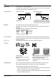
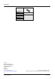
Technical design / mechanical design
Boiler flow from the right or left. The manual adjuster (DN 40 and DN 50), scale plate
and valve slipper can be re-positioned to suit the application
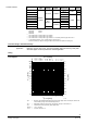
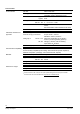
Sizing
40
60
100
200
300
400
600
1000
0.1
1
5
0
1
2
5
1
0
0
8
0
6
5
5
0
4
0
.
V [l/s]
100
1.0
p
v100
D
[bar]
0.1
0.001
0.01
0.2
0.02
0.002
0.3
0.03
0.003
0.5
0.05
0.005
0.007
0.07
0.7
277
167
111
55.5
27.7
16.7
5.55
11.1
2.77
1.67
1.11
0.56
0.28
0.17
D
N
4241D01
30
20
10
6
4
3
2
1
0,6
0.2
0.3
0.5
0.7
1
2
3
5
10
7
20
30
50
100
70
.
V [m
3
h
/
]
100
p
v100
D
[kPa]
Dp
max
= Maximum permissible differential pressure across the slipper valve’s control path, valid for the
entire actuating range of the motorized slipper valve
Dp
v100
= Differential pressure across the fully open slipper valve by a volume flow V
100
V
&
100
= Volumetric flow through the fully open slipper valve
100 kPa = 1 bar » 10 mWC
1 m
3
/h = 0.278 l/s water at 20 °C
Actuator overview
Application
Flow diagram