
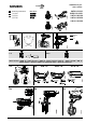
Mounting Instructions

Issued by
Siemens Switzerland Ltd
Smart Infrastructure
Global Headquarters
Theilerstrasse 1a
CH-6300 Zug
Tel. +41 58 724 2424
www.siemens.com/buildingtechnologies
© Siemens Switzerland Ltd, 2020
Technical specifications and availability subject to change without notice.
2 / 2 2022-02-22 A6V11162533_d A5W90003152_AC Siemens Smart Infrastructure
VAF41.150-360 + 2*GIB..1E
1b
2b
3b
4b
5b
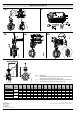
DN = Nominal size
H = Total actuator height plus minimum distance to the wall or the ceiling
for mounting, connection, operation, service, etc.
H1 = Dimension from the pipe centre to install the actuator (upper edge)
H2 = Dimension from the pipe centre to the top of the shaft
Type
DN
L
L1
L2
L3
D
n
D2
D4
D5
H
H1
H2
H3
Valve
Actuator
[mm]
[mm]
[mm]
[mm]
ø
[mm]
ø
[mm]
ø
[mm]
ø
[mm]
[mm]
[mm]
[mm]
[kg]
VAF41.65-63/1
GEB..1E
65
90
150
36
16
118
4
19
65
145
>550
153
331
226
5.8
VAF41.80-100/1
80
98
150
38
16
135
8
19
80
160
>560
161
339
234
7.1
VAF41.65-63/1
GCA..1E
ASK77.21
65
90
207
36
16
118
4
19
65
145
>550
153
351
246
5.8
VAF41.80-100/1
80
98
207
38
16
135
8
19
80
160
>560
161
359
254
7.1
VAF41.100-160
GIB..1E
100
115
207
44
18
155
8
19
100
180
> 570
171
369
264
9.1
VAF41.125-250
125
133
207
51
19
185
8
19
125
210
> 590
186
384
279
12.3
VAF41.150-360
2*GIB..1E
150
156
229
60
19
211
8
23
150
240
> 680
205
478
303
16.9
kg