
Data Sheet for Product

GAMMA instabus
Technical product information
June 2020
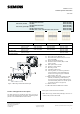
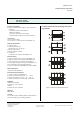
DELTA style wall switch, single
wall switch, double
wall switch, quadruple
Siemens Switzerland Ltd RS-AA
Building Technologies Division
International Headquarters
Theilerstrasse 1a © Siemens AG 2020 Update: http://www.siemens.com/gamma
CH-6300 Zug Subject to changes
9
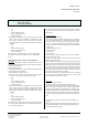
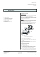
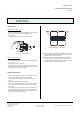
Unmounting
Without mounting screws
− Remove the wall switch (F5) completely with the frame
(F3) from the bus coupling unit (BTM) (F1):
a) manually
b) with a screw driver under the frame / wall
b)
a)
Figure 7: Unmounting
With mounting screws
− Remove wall switch buttons (F11), as described under
„mounting“.
− Remove mounting screws (F7).
− Snap switch buttons (F11) back onto the wall switch.
− Remove the complete switch module (F5) as described
under “Without mounting screws”
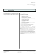
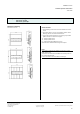
Address assignment
− Remove the transparent label cover (F8) with a screw
driver, while holding the switch module (F5).
Insert a screw driver as far as possible and turn it (fig-
ure 5).
− Remove the labels from the label base.
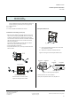
− Press the learning button (F9) on the device to initiate
the assignment of the physical address to the device
(figure 8).
− The programming LED (F10) turns on to indicate the
programming mode. Upon receiving the physical ad-
dress the device automatically returns to normal oper-
ating mode and the LED turns off.
Figure 8: Address assignment
F9 Learning button, for switching between normal op-
erating mode and addressing mode for receiving the
physical address (see picture 8)
F10 LED for indicating normal operating mode (LED off)
or addressing mode (LED on); upon receiving the
physical address the device automatically returns to
normal operating mode (see picture 8)